Table of Contents
Advertisement
Advertisement
Table of Contents

Summary of Contents for Wireless la5570
- Page 1 Wireless Home Security System User's Manual...
-
Page 2: Table Of Contents
Table of Contents Table of Contents Federal Communications Commission Interference Statement ... 3 Safety Precautions ..................4 Chapter 1: Introduction ................5 1.1 Features ....................... 5 1.2 Products List ....................6 1.3 System Architecture ..................7 Chapter 2: Getting Started ............... 8 2.1 Gateway Configuration ................ -
Page 3: Federal Communications Commission Interference Statement
FCC Statement Federal Communications Commission Interference Statement This equipment has been tested and found to comply with the limits for a Class B digital device, pursuant to Part 15 of the FCC Rules. These limits are designed to provide reasonable protection against harmful interference in a residential installation. -
Page 4: Safety Precautions
Safety Precautions Safety Precautions When using this device, basic safety precautions should always be followed to reduce the risk of fire, electric shock and injury to persons, including the following: Safety Considerations • Do not place this device on an unstable cart, stand, or table. The device may fall, causing serious damage to it. -
Page 5: Chapter 1: Introduction
• Touch-n-Play Installation: Easy to deploy the whole security system by touch-n-play installation. • Internet Access: Provide the lite function of wireless AP to allow Internet access by wired or wireless. • APP Software (iOS / Android): Easy to operate via APPs. -
Page 6: Products List
Wireless Gateway Wireless Panel Console Wireless Button Console (LA5570) (LA5572) (LA5573) Wireless Contact Sensor Wireless Pet Immune Motion Wireless Photoelectric (LA5584) Sensor (LA5582) Smoke Sensor (LA5587) Wireless CO , Temperature Wireless AI Transducer Wireless DI Transducer &... -
Page 7: System Architecture
Chapter 1: Introduction 1.3 System Architecture For details on the installation and configuration about the respective device, see “Chapter 2: Getting Started” on page 8. EN-7... -
Page 8: Chapter 2: Getting Started
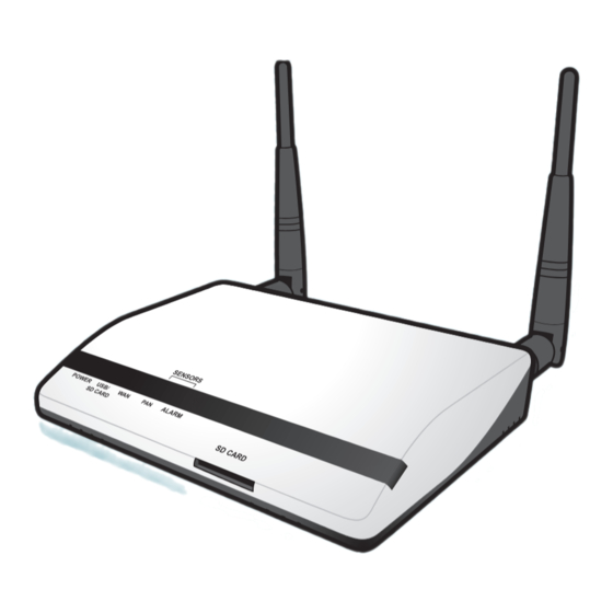
Chapter 2: Getting Started Chapter 2: Getting Started 2.1 Gateway Configuration This section provides a step-by-step guide to the installation and configuration of the Wireless Gateway. Accessories: Wireless Gateway Power adapter 2 Detachable antennas Stylus 2.1.1 Configuring Gateway Connection 1. Fasten both antennas on the back of the Gateway. - Page 9 4. Wait for around 60 seconds for the Gateway to boot up. The Power LED lights blue. 5. Start up your computer and enable the wireless network interface. Look for the wireless network icon at the bottom right of the screen.
- Page 10 7. Choose the Gateway SSID, and click Connect. 8. Enter the password and tap OK. Note • The default wireless network setting of the gateway: SSID: TECHview Password: (none) IP address: 192.168.19.254 9. Start your web browser. (It is recommended to use IE7.0 or above) 10.
- Page 11 12. Enter the password and click LOGIN. The default password is “123”. 13. After passed the password authorization, the home page of Wireless Home Turnkey System (WHTS) shows up on the screen. To change the appropriate settings, "4.1 System" on page 56..
-
Page 12: Device Joining
2.2 Device Joining All RF devices can be directly joined using the following 2 methods: Gateway or Router (Power Switching). With Router, it acts as a wireless hub for interconnecting sensors and gateway, and it also can expand communication coverage by cascading up to 3 routers. - Page 13 Chapter 2: Getting Started 3. Remove the sensor bracket if necessary. bracket S E T Wireless Contact Sensor 4. Short press the SET button at the back of the sensor. Wait until the LED indicator blinks green before releasing the SET button.
- Page 14 • For CO sensor, press both the and buttons until the screen blinks. Wireless Contact Sensor 5. To verify if the device binding process is successful, do one of the following: • Wait for few seconds until both indicators (on the router and device) turned off.
-
Page 15: Device Deletion
Chapter 2: Getting Started 2.2.3 Checking Device Received Signal Strength Indication (RSSI) Short press the SET button at the back of the sensor twice. The signal strength is indicated by its LED indicator. Status LED Color and Behavior Good Blinks green (very quickly) for 15 seconds. Normal Blinks green (quickly) for 15 seconds. -
Page 16: On-Site Installation
Chapter 2: Getting Started 2.4 On-Site Installation 2.4.1 Panel Console (LA5572) a. Mount the bracket on the wall. b. Open the battery cover and install the batteries into the battery compartments. Then close the bottom cover firmly. Note • The battery is designed for power backup and it will last for 2 hours. •... - Page 17 Chapter 2: Getting Started b. Button functions Button Press Long press (3 seconds) Full Arm Panic Partial Arm Disarm Off* * It needs to set up the link device to make the function buttons work. 2.4.3 Contact Sensor(LA5584) a. Install the battery into the battery compartment. (Attention: CR2032 battery positive side up) b.
- Page 18 Chapter 2: Getting Started c. Place the magnet on the door or window side. Align the arrow point of the reed by less than 10mm distance. Then stick on it. 10mm Close Open Note • Due to tamper-proof design, please make sure the installation is stable to avoid any false alarm.
- Page 19 Chapter 2: Getting Started b. The scan pattern is illustrated in the figure below. Detection area : (Unit=Meter) 10 11 12 13 Distance:10m 0 1 2 3 4 5 6 7 8 9 10 11 12 13 • The effective distance is 8~10m, at 2m height. •...
- Page 20 Chapter 2: Getting Started 2.4.5 Smoke Sensor(LA5587) a. Install the batteries into the battery compartments and close the bottom cover firmly. b. Mount the bracket on the ceiling. When the sensor detects the smoke, it will automatically trigger the alarm and also send out the signal to the Gateway. To manually turn off the alarm sound, push the button on the front side of the sensor.
- Page 21 Chapter 2: Getting Started b. Operation: Fan state Buzzer state Buzzer state current value Backlight: Green (normal) / Orange (warning) Temperature Humidity current value current value Setting buttons (a)Two level warnings and temperature unit setting: (1)Press the SET button once to access the level 1 (L1) warning threshold setup.
- Page 22 Chapter 2: Getting Started 2.4.7 Alarm Switch (LA5576) a. To power on the device, do one of the following: i. Plug in the power adapter to the device and the other side to the wall outlet. ii. Insert the batteries into the device. To insert the batteries, refer to the illustration below b.
- Page 23 Chapter 2: Getting Started 2.4.8 Power Switching(LA5578) a. Plug it into a wall socket and connect to any household appliance with less than 10A. b. Press the ON/OFF button to manually turn on/off the power relay. c. Power Meter: Plug the home appliance on LA5578. It can calculate the Voltage(V), Current(A), Power(W), Frequency(Hz) when the device is power ON.
- Page 24 Chapter 2: Getting Started The following devices are designed to be integrated with the 3rd party sensor once required. Please refer to "Chapter 6: Appendix" on page 107. for more details. 2.4.9 Analog Input (AI) Transducer a. Power on the device. b.
- Page 25 Chapter 2: Getting Started 2.4.10 Digital Input (DI) Transducer a. Install the battery into its compartment. (Attention: CR2032 battery positive side up) Install the battery. Then Remove the 3 screws Remove the back cover replace the back cover and attach the 3 screws. b.
- Page 26 Chapter 2: Getting Started 2.4.11 Lock Switch(LA5580) a. Power on the device. b. Connect the wiring pin of 3rd party lock. c. The Pin functions are as below: Wire 1- (Red) DC +12V Power Input Wire 2- (Black) Common Wire 3- (Yellow) Open Collect Digital Output (12V / 120mA Max.) Wire 4- (Green) Open/Close status 0V, 12V DC Level input (active high) Wire 5- (White) Lock/Unlock status 0V, 12V DC Level input (active high) d.
- Page 27 Chapter 2: Getting Started 2.4.12 Relay Switch(LA5577) a. Power on the adapter with a proper location. b. Connect the wiring pin of 3rd party device by DI/DO (dry contact). c. The description of integration and wiring as example: SET: blinking when joining Reboot: blinking when reboot Wire 1- DC +12V: Power Input Wire 2- GND: Common...
- Page 28 Chapter 2: Getting Started 2.4.13 Power Relay Module(LA5575) a. Power on the adapter with a proper location. b. Connect the wiring pin of 3rd party device by DI/DO (dry contact). c. The description of integration and wiring as example: Wire 1- AC IN: 100VAC~240VAC Wire 2- AC IN: 100VAC~240VAC Wire 3- K1: Dry Output 1 Dry contact Wire 4- K1: Dry Output 1 Dry contact...
-
Page 29: Surveillance Configuration
2. To obtain the IP camera MAC address and configure related IP camera settings, refer to "4.7 Surveillance" on page 90.. 3. Reboot both Gateway and IP camera to take effect. 2.5.2 Wireless Configuration WiFi 1. Connect the Gateway and the IP camera by using an Ethernet cable. - Page 30 Chapter 2: Getting Started 3. Enable IP camera wireless function then select the Gateway as an access point (AP). 4. Disconnect the Ethernet cable. Then reboot both Gateway and IP camera to take effect. 2.5.3 Wireless via WPS Configuration 1. Make sure your WLAN security type is WPA. Refer to "4.1.4 WLAN" on page 60.
-
Page 31: Chapter 3: App Management
Chapter 3: APP Management Chapter 3: APP Management 3.1 Download APP on Smart Handheld Device By using APP, you can view the sensors status, video live view, and access the Web Management remotely to monitor your home and family at anytime and anywhere. -
Page 32: Network Setting
Chapter 3: APP Management 3.2 Network Setting For Wi-Fi connection (local use), set your phone Wi-Fi setting to connect to the gateway’s SSID. Once connected, you may have to enter the encryption key once required. Note • Default SSID is “TECHview” and no encryption key. •... - Page 33 Chapter 3: APP Management 3.4 Login Page 1. Touch the APP icon ( ) to enter the login page. 2. Enter the Gateway “Domain Name or IP” and “Password” to login. Note • You may turn on “Remember Password” function to retain the password for the next time login.
- Page 34 Chapter 3: APP Management Once the system detects any changes on the WAN IP, the APP will push a message to notify user. User may enter the specific IP / Gateway Domain Name directly. 3.6 Push Notification Setting (iOS) When first time login the APP, it will automatically register the push notification service and enable the function automatically.
- Page 35 Chapter 3: APP Management 3.7 Push Notification Setting (Android) When first time login the APP on an Android device, a pop-up message appears on the screen to confirm if you’re allowed to turn on the push notification service. Click YES to continue. Check to enable Wait for a while to let the system...
- Page 36 Chapter 3: APP Management 3.8 Push Notification When some events are detected, the gateway will automatically send out the push messages to your smart handheld device in minutes, even when the APP is off-line. Current Several notification notifications (unread) 3.9 Main Page Refresh Options Function bar...
- Page 37 Chapter 3: APP Management 3.10 Panic Touch and hold the Panic icon (shown on the function bar) for a few seconds, then it will trigger alarm immediately. 3.11 Arming/Disarming Touch the Arm/Stay or OFF icon to arm or disarm the system. Main page Full Arm mode Partial Arm mode...
- Page 38 Chapter 3: APP Management 3.12 Sensor State Error While arming, the system will check all contact sensors’ state first and display an error message if any of the sensor is detected in “open” state. 3.13 Alarm Trigger Once any alarm is triggered, a pop-up message will appear on the screen, the system will send out a push message to your smart handheld device, and all related device icons will change to Green...
- Page 39 Chapter 3: APP Management 3.14 Refresh Click the Refresh icon to manually refresh all status immediately. Refresh The auto refresh timer is approximately 5~15 seconds by default. If you quick-click the Refresh icon for three times, the system will pop-up the “Prompt” window to confirm the connection.
-
Page 40: Device Information
Chapter 3: APP Management 3.15 Rename Touch and hold the desired device icon and the rename dialog box appears on the screen. Enter the new name using the on-screen keyboard. You may also customize the name in any language (i.e. Chinese) supported by your smart handheld device. - Page 41 Relay Switch and Power Relay Module are DI/DO device types. Click it to see the setup detail. Relay Switch Relay Switch Power Relay Module 3.18 Switch On/Off For automation-type controllers (such as Wireless Power Switching or Wireless Lock Switch), you can manually turn on/off the device switch. EN-41...
- Page 42 Chapter 3: APP Management Select and touch the switch device icon once, then slide it to turn ON or OFF. <Power Off> <Power On> Siren can be turned ON or OFF randomly by touching the “Siren” icon. 3.19 Current Power Status When power switching is turned on, the current measured value will show voltage, current, power, and frequency.
-
Page 43: Schedule Setup
Chapter 3: APP Management Select Schedule to set the schedule to let the device to automatically turn the switch on/off. 3.21 Schedule Setup You can set up to 2 schedules per day. Set the desired schedule to ON and touch to access the time and day setup. Specify the Start and End time, then select the desired day. - Page 44 Chapter 3: APP Management 3.22 Power Meter and Cumulative Usage Touch Usage to select the cumulative period to calculate. The total spent energy and cost will be displayed. <Scroll to select> <Scroll to select> The maximum cumulative period is 3 months, and the earliest month shown on the screen is 12 months ago.
- Page 45 Chapter 3: APP Management 3.23 Video Live View Select and touch IP camera’s icon to display the live video. To view the live image of any camera on full screen, hold your smart handheld device horizontally for better viewing. Full screen Normal view 3.24 Taking Screenshot For iPhone/iPad, press both Power and Home buttons to capture a...
- Page 46 Chapter 3: APP Management 3.25 Device Disconnected The device icon will be showed in GREY once disconnected from the Gateway. If this happens, check if the power supply is unplugged or the battery power is low on each disconnected sensor. 3.26 Options Touch Options (on the top-left) to show the sub-function page.
-
Page 47: Zone Setup
Chapter 3: APP Management 3.27 Zone Setup Touch Zone Settings to enter the zone setup page. You may choose the zone name, devices to apply (the icon will appear on the screen), and enable the specific zone will be armed while Partial Arming. <Specify zone name>... - Page 48 Chapter 3: APP Management 3.28 Switch Link Touch Switch Link to configure the link setup. Select the sensor first, then select the switch to link, up to 5 switches. The icon will appear on the screen. • By default the switch is set to ON. A power icon ( ) at the right-bottom indicates the power is on.
-
Page 49: System Log
Chapter 3: APP Management 3.29 Camera Link Touch Camera Link to configure the camera setup. Select the camera first, then select the sensor to link. The icon will appear on the screen. Touch OK to confirm. Linked sensors 3.30 System Log Touch Options >... -
Page 50: Network Information
Chapter 3: APP Management 3.31 Video Event Touch Options > MISC SETTINGS > Video Event to view the event-trigger video list. To play back the video, select the desired event and the video playback starts. Full screen Event-trigger video list 3.32 Network Information Touch Options >... - Page 51 Chapter 3: APP Management 3.33 Website Interface Touch Options > MISC SETTINGS > Network Information > Website to enter the Gateway Web Management for changing the necessary settings (if required). The details on how to configure settings on the respective sensor, see Chapter 4: Web Management on page 56.
-
Page 52: Network Settings
Chapter 3: APP Management 3.35 Login Password Touch Options > MISC SETTINGS > Login Password to change the password. The default password is “123”. Note • The password must be at least 3 numeric characters. The maximum password length is 12. 3.36 Network Settings Touch Options >... - Page 53 Chapter 3: APP Management Enter the Wi-Fi SSID name and password. Then reboot the system to make the setting takes effect. PPPoE DHCP Note • If the WAN mode is set to “Static IP”, you have to access the Web Management to change the network setting.
-
Page 54: System Configuration
Chapter 3: APP Management 3.38 System Configuration Touch Options > MISC SETTINGS > System Configure to backup/restore the system settings. Select Backup Configure to save the current system configuration settings. Select Restore Configure to restore the settings that you have saved earlier. - Page 55 Chapter 3: APP Management 3.39 Logout Touch Options > LOGOUT to log out of the APP. Then touch Logout to confirm. EN-55...
-
Page 56: Chapter 4: Web Management
Chapter 4: Web Management Chapter 4: Web Management 4.1 System After completed the initial Gateway configuration (see 2.1 Gateway Configuration on page 8), you can now connect to the Gateway via HTTP web browser. In the home page of the WHTS, the left navigation bar shows the menu options to configure the system. - Page 57 Chapter 4: Web Management 4.1.2 WAN This option allows you to configure the Gateway WAN interface. There are three available options. Depending on what internet service provider you choose, you can use one of them to connect to Internet. • DHCP This option allows the Gateway to obtain an IP address dynamically via DHCP.
- Page 58 Chapter 4: Web Management • Static IP This option allows you to configure the Gateway WAN interface using a fixed IP address. 1. Select System > WAN > Static IP. 2. Enter the information for IP Address, Subnet Mask, Default Gateway IP, and DNS IP Address as assigned.
- Page 59 Chapter 4: Web Management 4.1.3 LAN This option allows you to configure the Gateway LAN interface. 1. Select System > LAN. 2. Enter IP Address and Subnet Mask as your preferred. The default IP address is “192.168.19.254”. 3. Click Apply. Note •...
- Page 60 Chapter 4: Web Management 4.1.4 WLAN This option allows you to configure the Gateway Wireless LAN interface. 1. Select System > WLAN. 2. Check Enable Wireless LAN Interface to enable the Wireless LAN. 3. Enter SSID. The default SSID for the Gateway is “TECHview”.
- Page 61 Chapter 4: Web Management 4.1.5 DDNS This option allows you to configure the Gateway Dynamic DNS (DDNS) information. 1. Select System > DDNS. 2. Check Enable to enable DDNS Service. 3. Select the DDNS service provider’s domain name in the Dyndns System field.
- Page 62 Chapter 4: Web Management Note Creating a DDNS Domain Name 1. Start your web browser and enter http:dyn.com/dns 2. Select Devices Remote Access. 3. Fill in the necessary data and follow the on-screen instruction to create a Dyn account. EN-62...
- Page 63 Chapter 4: Web Management 4. Enter the confirmation code to confirm your account. Note • A confirmation code will be sent to your e-mail account. 5. Click PROCEED TO CHECKOUT to continue. 6. Fill in the payment information and click PLACE ORDER. Note •...
- Page 64 Chapter 4: Web Management 7. Create a new hostname and click Activate. Enter a hostname and IP address and select a DDNS server. After all settings are complete, the DDNS alias will be the combination of “hostname” and “DDNS server”. For example: Hostname: xxx;...
- Page 65 Chapter 4: Web Management 4.1.6 DHCP Leasing This option displays the Gateway DHCP client information. 1. Select System > DHCP Leasing. 2. Click Renew to renew the Gateway DHCP client information. Note • The first IP address shown on the above illustration as “Always” belongs to an IP camera.
- Page 66 Chapter 4: Web Management 4.1.8 Log Server This option allows you to set up the external Syslog server information. There are two available options: Syslog and SIA. Select System > Log Server. Syslog This option allows you to configure the external log server information. 1.
- Page 67 Chapter 4: Web Management This option allows you to configure the external SIA server information. 1. Select SIA. 2. Enter the IP address or Domain name, SIA port number, Account number and prefix, and specify the receiver number. 3. Click Apply. EN-67...
-
Page 68: Event Log
Chapter 4: Web Management 4.1.9 Event Log This option displays the latest fifty (50) event logs. 1. Select System > Event Log. 2. Click to delete all event logs. Note • All logs are automatically saved into the SD card installed on the Gateway. (50 logs per file and more than 1,000 logs could be saved). - Page 69 Chapter 4: Web Management 4.1.10 Information This option displays the Gateway information (software version, network, and SSID). Select System > Information. 4.1.11 Upgrade This option allows you to upgrade the Gateway software. a. Upgrade by USB pen drive 1. Select System > Upgrade. 2.
- Page 70 Chapter 4: Web Management b. Upgrade by remote site 1. Select System > Upgrade. 2. Save the firmware file (*.pck) to your computer. 3. Click the Browse button to select the latest firmware file. Then press Select to confirm the selection. 4.
- Page 71 Chapter 4: Web Management 4.1.13 Reset This option allows you to reset all settings to the factory default. 1. Select System > Reset. 2. To reset the system, click Reset. 3. A pop-out message “Do you really want to reset the system?” to re-confirm again.
-
Page 72: Arm Mode
Chapter 4: Web Management 4.2 Arm Mode This option allows you to select the alarm mode. 1. Be sure that the Alarm Controller configuration is successful. See 2.2 Device Joining on page 12. 2. Select Arm Mode. 3. Select the desired alarm mode (Disarm/Partial Arm/Full Arm). •... -
Page 73: Alarm Delay
Chapter 4: Web Management 4.3 Alarm Delay This option allows you to configure the outgoing/incoming alarm delay time once the sensor triggered. 1. Select Arm Delay. 2. Set the delay time to activate the alarm mode. 3. Select the desired sensor on Sensor Delay List. (This option is only applicable for Contact sensor or Pet Immune Motion sensor.) 4. -
Page 74: Sensor
Chapter 4: Web Management 4.4 Sensor This option allows you to configure the device binding settings. The compatible device types include the following: Wireless Panel Console, Wireless Button Console, Wireless Contact Sensor, Wireless Pet Immune Motion Sensor, Wireless Photoelectric Smoke Sensor, Wireless CO Sensor, Wireless AI Transducer, Wireless DI Transducer, and Wireless Relay DI. - Page 75 Chapter 4: Web Management 4.4.1 Panel Console This option allows you to configure the Wireless Panel Console settings. 1. Click 2. Select the location, device number, and specify the sensor name. Click on the pull-down menu to see more options.
- Page 76 Chapter 4: Web Management 4.4.2 Button Console This option allows you to configure the Wireless Button Console settings. 1. Click 2. Select the location, device number, and specify the sensor name. Click on the pull-down menu to see more options.
- Page 77 Chapter 4: Web Management 4.4.3 Contact Sensor This option allows you to configure the Wireless Contact Sensor settings. 1. Click 2. Select the location, device number, and specify the sensor name. Click on the pull-down menu to see more options.
- Page 78 Chapter 4: Web Management 4.4.4 PIR Motion Sensor This option allows you to configure the Wireless Motion Sensor settings. 1. Click 2. Select the location, device number, and specify the sensor name. Click on the pull-down menu to see more options.
- Page 79 Chapter 4: Web Management 4.4.5 Smoke Sensor This option allows you to configure the Wireless Smoke Sensor settings. 1. Click 2. Select the location, device number, and specify the sensor name. Click on the pull-down menu to see more options.
- Page 80 Chapter 4: Web Management 4.4.6 Carbon Dioxide (CO ) Sensor This option allows you to configure the Wireless Carbon Dioxide Sensor settings. 1. Click 2. Select the location, device number, and specify the sensor name. Click on the pull-down menu to see more options.
- Page 81 8. Click Apply to save the settings. 4.4.7 AI Transducer This option allows you to configure the Wireless AI Transducer settings. 1. Click 2. Select the location, device number, and specify the sensor name. Click on the pull-down menu to see more options.
- Page 82 9. Click Apply to save the settings. 4.4.8 DI Transducer This option allows you to configure the Wireless DI Transducer settings. 1. Click 2. Select the location, device number, and specify the sensor name. Click on the pull-down menu to see more options.
- Page 83 8. Click Apply to save the settings. 4.4.9 Wireless Relay DI This option allows you to configure the Wireless Relay DI settings. 1. Click 2. Select the location, device number, and specify the sensor name. Click on the pull-down menu to see more options.
- Page 84 Chapter 4: Web Management 4. In the Alarm Type field, check Anti-disaster when connecting with the third party disaster sensor. (The DI sensor will be ready to alarm all the time.) 5. To bind multiple links with the automation-type controllers to enable remote automatic control, select the controller ID in the Switch link field and click Add.
-
Page 85: Siren
Chapter 4: Web Management 4.5 Siren This option allows you to configure the Wireless Alarm Controller settings. 1. Be sure to complete the siren configuration (See 2.2 Device Joining on page 12). 2. Select Siren. Controller name and ID Alarm is triggered Alarm is activated 3. -
Page 86: Automation
3. You can click device status to turn on/off the automation device manually. 4.6.1 Remote Power Meter Switch This option allows you to configure the Wireless Power Meter Switch settings. 1. Click 2. Select the location, device number, and specify the sensor name. - Page 87 The total energy consumption and cost are displayed in the Total energy used and Total amount fields. 4. Click Apply to save the settings. Note • By this automation feature, you may power control your in-house lighting, or device remotely. Wireless Power Meter Wireless Gateway Switch Auto lighting EN-87...
- Page 88 5. Click Apply to save the settings.If the Schedule 1 and Schedule 2 are overlap, the system cannot save the settings. 4.6.2 Lock Switch This option allows you to configure the Wireless Lock Switch settings. 1. Click 2. Select the location, device number, and specify the sensor name.
- Page 89 Note • The Lock Controller is used to integrate with electronic lock and transform the signal into wireless control signal. See 6.1 3rd-Party Sensor Integration on page 107. 4.6.3 Wireless Relay DO This option allows you to configure the Wireless Relay DO settings.
-
Page 90: Surveillance
Chapter 4: Web Management 4.7 Surveillance This option allows you to configure both the 3rd-party wireless and wired IP camera, change its settings, and view live video via web browser. 1. Be sure to complete the IP camera configuration. See 2.5 Surveillance Configuration on page 29. - Page 91 Chapter 4: Web Management 2. After the IP camera links to the Gateway via DHCP, the IP camera MAC address will appear on the list. Click Renew to renew the list. 3. Click the MAC address and it will automatically fill the setup parameters. Then confirm the Name, address, and Port mapping...
- Page 92 Chapter 4: Web Management However, if the IP camera is not fully compatible with the Gateway, click “IP camera name” and configure the necessary settings. IP camera name IP address of the IP camera Access stream name IP camera RTSP port number Gateway RTSP port number IP camera HTTP port number Gateway HTTP port number...
- Page 93 Chapter 4: Web Management 4.7.2 Monitoring This option allows you to view live video via either RTSP mode or HTTP mode. 1. To view live video, select Monitoring. 2. Click “IP camera name” to display video via RTSP mode. Click to display video via HTTP mode.
- Page 94 Chapter 4: Web Management Live view via RTSP mode Live view via HTTP mode EN-94...
- Page 95 Chapter 4: Web Management 4.7.3 Event This option allows you to view the recorded videos or save the recorded file into your computer. 1. To view recorded videos, select Event. 2. Click to play back the recorded file. 3. Right-click on and select “Save target as”...
-
Page 96: Notification
Chapter 4: Web Management 4.8 Notification This option allows you to configure e-mail notification settings. 4.8.1 Email This option allows you to configure e-mail notification settings. 1. Select Notification > Email. 2. Check Enable to enable e-mail notification service. 3. Enter SMTP server’s IP address or Domain Name in the SMTP Server field. -
Page 97: Security Zone
Chapter 4: Web Management 4.9 Security Zone This option allows you to configure the security zone. 1. Select Security Zone. 2. Select the location. 3. Click on the pull-down menu to see more options. To customize the zone name, select Other and enter the desired zone name. -
Page 98: Logout
Chapter 4: Web Management 4.10 Logout This option allows you to log out of the system. Select Logout. EN-98... -
Page 99: Chapter 5: Panel Console Management
Chapter 5: Panel Console Management Chapter 5: Panel Console Management Using wireless panel console (LA5572), you can also operate the system functions. 5.1 Device Configuration This section provides a step-by-step guide to configure LA5572 with the gateway. 1.> Press the SET button on the gateway for 2 seconds. The Alarm LED lights red shortly. - Page 100 Chapter 5: Panel Console Management Note • LA5572 supports both city power and battery (alkaline AA battery x 2, non-rechargeable, for 2 hours emergency use). • Once LA5572 is unexpectedly unplugged from the bracket under system arm mode, the tam- per-proof detection will trigger the alarm.
-
Page 101: Menu Navigation
Chapter 5: Panel Console Management 5.3 Menu Navigation Press the button and key in the password to enter the menu mode. FUNC > Automation Sensor Menu options The following table describes the available menu options: Menu Sub-menu Description Automation Display a list of binding automation-type Automation List devices and display the device status. - Page 102 Chapter 5: Panel Console Management 5.4 Using the AWAY/STAY Button To activate the alarm: Press the button to enable choose the arm mode (AWAY AWAY STAY means Full ARM, STAY means Partial ARM) mode. Fix the Press error state ENTER on-site.
- Page 103 Chapter 5: Panel Console Management 5.5 Using the Panic Button To trigger emergency alarm immediately: • Press and hold the button for 3 seconds. PANIC To deactivate the alarm: • Enter the password and press the button. PANIC ALARM! DISARM Password: DISARM...OK! PANIC “***”...
- Page 104 Chapter 5: Panel Console Management 5.7 Operating Tips The following messages that you may meet while using LA5572. a. When the battery power is low, a “Low Battery!” message will display on the screen to remind. b. If you remove the wall-mount bracket while arming or other device tamper proof (i.e.
- Page 105 With the hotkey features, you can use a combination of keys to access or control the specific device. The hotkey list as the following: Combination keys Device Type “C” + “1” Wireless Temperature/Humidity Sensor “C” + “2” Wireless Power Switching “C” + “3” Wireless Lock Switch “C” + “4”...
- Page 106 Chapter 5: Panel Console Management 5.9 Device Operation Detail Main Function Sub-Tree 1 Sub-Tree 2 Sub-Tree 3 LA5578 Status LA5578 Status: LA5578-xxxxxx LA5578 Value Open vClose LA5580 Status: LA5580 Value: LA5580-xxxxxx Open vClose 220V / 1.5A / 330W LA5577-xxxxxx LA5577-xxxxxx LA5577 Status: Automation LA5577-xxxxxx...
-
Page 107: Chapter 6: Appendix
The following sensor types are designed to be integrated with the 3rd-party sensor once required. Sensor type 3rd-party sensor Wireless AI Transducer i.e. 4-20mA CO Detector, Gas Detector, or Temperature Sensor Wireless DI Transducer i.e. NC/NO CO Detector, Smoke Detector,... - Page 108 Chapter 6: Appendix AI/DI Transducer and Lock Switch Applications 4-20mA CO Detector 4-20mA Gas Detector Temperature Sensor Electronic Lock AI Transducer AI Transducer AI Transducer Lock Controller NC/NO CO Detector NC/NO Smoke Detector NC Fire Alarm NC/NO Gas Detector DI Transducer DI Transducer DI Transducer DI Transducer...
- Page 109 Chapter 6: Appendix AI Transducer Integration (Temperature Sensor) power supply 15...40VDC 24VAC 20% AI Transducer DC12v 4-20mA current Yellow Adapter Black DI Transducer Integration (CO Sensor) EN-109...
- Page 110 Chapter 6: Appendix DI Transducer Integration (Smoke Sensor) Lock Switch Integration EN-110...
- Page 111 Chapter 6: Appendix Relay Switch (LA5577) Power Relay Module (LA5575) EN-111...
-
Page 112: Troubleshooting
Chapter 6: Appendix 6.2 Troubleshooting This section contains a common troubleshooting tips that you may meet while using WHTS system. If you need additional helps, please contact our partner. Problem Solutions Cannot access the WHTS web Check if the AP (SSID) is correct console or APP. - Page 113 Chapter 6: Appendix Problem Solutions The device is disconnected. Re-bind this device to re-active the connection. See 2.2 Device Joining on page 12. The Contact Sensor status is in Place the magnet closer to the “open” mode. Contact Sensor main unit and click Refresh on the web console.
- Page 114 Chapter 6: Appendix Problem Solutions Got an error message when Set the Contact Sensor to “close” enabling the arm mode to Partial mode. Arm or Full Arm. Note: When the Contact Sensor is in “open” mode, you cannot enable Partial Arm and Full Arm mode. Cannot access the WHTS web Unplug the power adapter from the console even if the AP (SSID) is...
- Page 115 Chapter 6: Appendix Problem Solutions Forgot the password. Press the SET button for 15 seconds to restore the factory default settings. Cannot upgrade the Gateway A password is required before firmware. updating the firmware. Please contact the manufacturer for more information.
Need help?
Do you have a question about the la5570 and is the answer not in the manual?
Questions and answers