
Summary of Contents for kauoheng KH-313 SERIES
- Page 1 KAUOHENG KH-313 SERIES OPERATION MANUAL 電腦橫編織機 COMPUTERIZED FLAT KNITTING MACHINE...
-
Page 2: Dear Customer
DEAR CUSTOMER: Welcome to be an owner of KH-313 series computerized flat knitting machine as Kauo Heng endeavors to maintain a high standard of this machine, we also pleased for your cooperation to make the machine serve longer by reading this operator manual carefully before commencing your production. -
Page 3: Overview Of Kh-313 Series
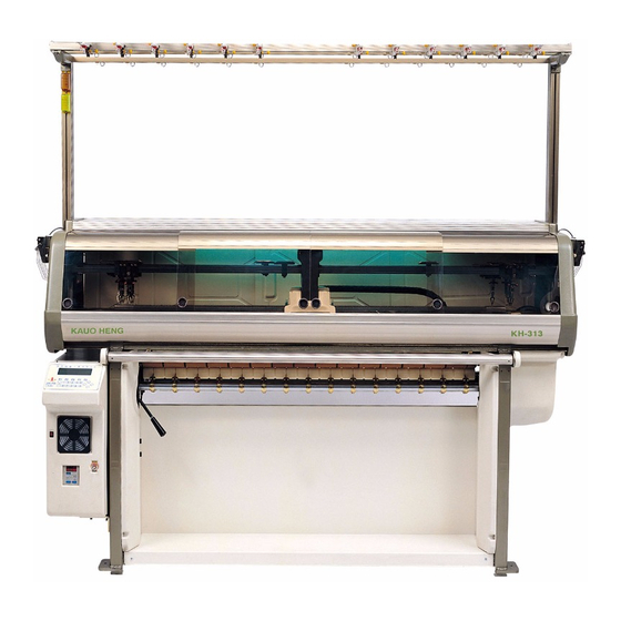
OVERVIEW OF KH-313 SERIES 1. Yarn carrier selection 2. Carriage 3. Operation bar 4. Main cover 5. Fabric take-down roller 6. Controller 7. Main motor 8. Side tension 9. Top tension 10. Side cover... -
Page 4: Points To Observe
1. Points to observe Installation Environmental Conditions ○ Please install the machine as below instructions in order to use this machine in the best condition for a long period of time. Do not install the machine at a place subject to direct sunshine and/or adjacent to a heat generation source such as a furnace/oven. -
Page 5: Installation
Fig.1.1 illustrates the correct position of jacking while moving the ○ machine. It is very important when moving the machine. The yarn carrier rail shall never be used to push the machine since it will distort the rail. Fig.1.1Correct position of jacking the machine When connecting the electric power, attention must be paid to the ○... -
Page 6: Operation
3. Operation 3.1 Power switch As Fig.3.1 front sideof controller, easily find two switches. Filp upward is “ON” and downward is “OFF”. Fluorescent lamp switch Breaker/power switch Fig.3.1 Front side of controller 3.2 Operation bar Inching:When turning forward of the operation bar, machine operates ○... - Page 7 3.3 Yarn feeder The position of carrier is adjusted according to the desired knitting width, correctly make yarn feeder beside the end working needle by 10 ㎜.The yarn feeder must be in the central position between front and rear needles, also check its height refer to Fig.3.3.When work several yarn feeder in knitting, the position of carrier should be adjusted to make each yarn feeder not be overlapped, it avoids damage of the parts.The yarn carrier on rail must be adjusted in easy...
- Page 8 3.4 Top tension Top tension springs should have the correct tension, the opening of the knot-catcher must be set according to the yarn count that is being knit-ted. Tension adjust dial Knot catcher adjust Tension disk Knot catcher Fig.3.5 Top tension 3.5 The latch brush Latch brush is important to prohibit the needle latch to close in knitting, the correct brusk setting is illustrated in Fig.3.6.
-
Page 9: Clear Filter
4. Clear filter Filters are equipped in the controller and in the parts of main motor, it prohibits dust to come inside. Please take out the filter and dust it offen refer to Fig.4.1. Filter Fig.4.1 Cleaning filter 5. Needle bed 5.1 KH-313 needle bed KH-313 the structure of front and rear needle bed is the same with regular needle high butt and low butt. - Page 10 For the knitting needles in unused you don’t need to dismantle them. All you have to do is to push them in the unactive position. In Fig.5.2 take out the steel wire firstly, and push to the shown area and replace the steel wire.
-
Page 11: Cam Plate Distance
6. Cam plate distance The distance between cam plate and needle bed is maximum 0.15 ㎜, Fig.6.1 shows how to check and adjust.Please check it by every 3 months, loosen the stepped screw and turn the bearing pin to adjust the distance, make sure to tighen the stepped screw after adjustment. -
Page 12: Fabric Take-Down System
8. Fabric take-down system In principle of the take-down tension strength must be small and average. The take-down system is controlled by torque motor. There are two important things to adjust the take-down tension strength. First method is the two speeds No.1 and No.2 as Fig.8.1 adjust each with turning knob and set the speed, the tension strength is larger and the speed is faster. -
Page 13: Racking Mechanism
9. Racking mechanism The rear bed can be racked five (5) pitches, the initial position”0”. See ○ the left selvedge of needle bed, the corresponding position that the first needle of rear is on the left hand side of the first needle of front. As shown in Fig.9.1. - Page 14 10. KH-313 Cam system KH-313 the cam system of front & rear needle bed is the same. Fig10.1 is overview of front & rear cam system. Fig.10.1 Front & rear cam system Bridge cam Needle clearing cam Needle raising cam Stitch cam Stitch cam Needle guide cam...
- Page 15 11. KH-313 Cam action n graphs show the usual kinds of cam active situation. “ARROW” means the carriage knitting direction. Cam of “slant-line” area is in half raising, and also the position of low butt needle “miss” and high butt needle “knit”. Cam of “cross-line” area is in raising position and all butt needles are without any action.
- Page 16 KH-313 Fig.11.3 Command 2:All butt needle TUCK Fig.11.4 Command 3:High butt needle KNIT 1-13...
- Page 17 KH-313 Fig.11.5 Command 4:High butt needle KNIT Low butt needle TUCK Fig.11.6 Command 5:High butt needle TUCK 1-14...
- Page 18 12. KH-313J Cam system KH-313J the cam system of front & rear needle bed is the same. Fig12.1 is overview of front & rear cam system. Fig.12.1 Front & rear cam system Bridge cam Needle clearing cam Needle raising cam Stitch cam Stitch cam Needle guide cam...
- Page 19 13. KH-313J Cam action n graphs show the usual kinds of cam active situation. “ARROW” means the carriage knitting direction. Cam of “slant-line” area is in half raising, and also the position of low butt needle “miss” and high butt needle “knit”. Cam of “cross-line” area is in raising position and all butt needles are without any action.
- Page 20 KH-313J Fig.13.3 Command 2:All butt needle TUCK Fig.13.4 Command 3:High butt needle KNIT 1-17...
- Page 21 KH-313J Fig.13.5 Command 4:High butt needle KNIT Low butt needle TUCK Fig.13.6 Command 5:High butt needle TUCK 1-18...
- Page 22 KH-313J Fig.13.7 Command 6:Jack KNIT Fig.13.8 Command 7:Jack TUCK 1-19...
- Page 23 14. KH-313TJ Front cam system Fig14.1 is overview of front cam system. Fig.14.1 Front cam system Bridge cam Needle clearing cam Needle raising cam Stitch cam Stitch cam Needle guide cam Needle guide cam Stitch guide cam Stitch guide cam Jack raising cam Jack guide cam Jack guide cam...
- Page 24 15. KH-313TJ Rear cam system Fig15.1 is overview of rear cam system. Fig.15.1 Rear cam system Bridge cam Needle clearing cam Needle raising cam Stitch cam Stitch cam Needle guide cam Needle guide cam Stitch guide cam Stitch guide cam Jack raising cam Jack guide cam Jack guide cam...
- Page 25 16. KH-313TJ Cam action n graphs show the usual kinds of cam active situation. “ARROW” means the carriage knitting direction. Cam of “slant-line” area is in half raising, and also the position of low butt needle “miss” and high butt needle “knit”. Cam of “cross-line” area is in raising position and all butt needles are without any action.
- Page 26 KH-313TJ Fig.16.3 Command 2:All butt needle TUCK Fig.16.4 Command 3:High butt needle KNIT 1-23...
- Page 27 KH-313TJ Fig.16.5 Command 4:High butt needle KNIT Low butt needle TUCK Fig.16.6 Command 5:High butt needle TUCK 1-24...
- Page 28 KH-313TJ Fig.16.7 Command 6:Jack KNIT Fig.16.8 Command 7:Jack TUCK 1-25...
- Page 29 KH-313TJ Fig. 16.9 Command 8:Transfer of rear bed & receipt of front bed 1-26...
- Page 30 KH-313TJ Fig.16.10 Command 8:Transfer of front bed & receipt of rear bed 1-27...
- Page 31 INSTRUCTION MANUAL 0.START 1.EDIT 2.RUN 3.FILE 2-11 4.FUNCTION 2-14 5.TEST 2-15...
-
Page 32: Instruction Explanation
INSTRUCTION EXPLANATION Yarn carrier Rear stitch Rear cam Knitting speed Line No. Repeat start-line Repeat count Repeat end-line Racking Front cam Take-down speed Front stitch 0. None yarn carrier Yarn carrier 1~9 KH-313 KH-313J KH-313TJ 0. Miss 0. Miss 0. Miss 1. - Page 33 0. START Fig.0-1 When turning on the machine, it will appear this screen and display main menu after you press any key. When you switch on the machine, then it displays 【MEMORY ERROR】 or 【 FILE ERROR】 , you must switch off the machine and contact our agent or our service department.
- Page 34 1.1 OPEN:Open file Press in edit menu, and then the screen displays as Fig.1-2. Fig.1-2 Remark:In screen there are five small squares, each one corresponds to on keyboard, blank means out of function. For ~ example, in Fig.1-2, is SURE, are blank ~...
- Page 35 INSTRUCTION EXPLANATION Yarn carrier Rear stitch Rear cam Knitting speed Line No. Repeat start-line Repeat count Repeat end-line Racking Front cam Take-down speed Front stitch FILE:Insert a file. Fig.1-5 Insert file LINE:After current editing line inset a “ blank line ”, and the following lines are backward.
- Page 36 DEL:Delete indicated lines. Fig.1-7 EXIT:Press EXIT then the system will ask you to save this file, if it is not a new file, directly press SURE to use the same file name to save. The screen displays as Fig.1-9 then press If you don’t want to save, press twice to exit.
- Page 37 1.2 NEW:Open file After you edit the first line, press to insert blank line and go on editing. Fig.1-11 1.3 SHIFT:This function will copy left system to right system, or right system to left system, it contents of copy including cam, stitch, yarn carrier.
- Page 38 2. RUN Fig.2-0 Press ☉Enter RUN mode, if the stepping motor is not at home position, it displays warning 【STEP ERROR】 . You should go to the TEST mode, in STITCH function, you can test the stepping motor then come back to RUN mode.
-
Page 39: Error Message
ERROR MESSAGE After you finish inputting the instruction for the program that occurs incorrect action or wrong instruction to the function of machine, it will automatically appear ERROR message on RUN mode. Error message table Message Explanation To edit a program, the total lines of program must be an even number. - Page 40 After finishing checking the system and confirming the program executive then the screen displays as Fig.2-1. Fig.2-1 Enter Fig.2-1, set the knitting file name, and then set T-PC (total pieces), F-PC (finished prieces), after setting press to enter Fig.2-2. Fig.2-2 RUN:Turn the operation bar for knitting.
- Page 41 EXIT: Fig.2-3Edit stitch value & knitting speed Press enter Fig.2-4 Press enter Fig.2-5 Fig.2-4 Fig.2-4displays all the used stitch value of file. Directly move the cursor to the area of being changed, and press the numeric key to correct it. For example, in Fig.2-4the 12 is replaced by 15, then all the stitch value 12 is/are changed with 15 in this file.
- Page 42 CORRECTIVE SIGNAL FAULT REMARK ACTION Yarn break T-TSN Tension loose Yarn knot Yarn break After corrective action, S-TSN Tension loose turn the operation bar to clear, and restart the Needle break DETR operation bar and go on Fabric rise knitting. Fabric fall TK-DN Fabric roll-up...
- Page 43 3. FILE Fig.3-1 3.1 DISP:Display Move cursor to select the displayed file name, and press SURE the system will execute program once simultaneously, and display screen Fig.3-4. In Fig.3-4, column 1 displays file name and it’s size of used memory. Column 2 displays the beginning position of yarn carrier on the left and the right.
- Page 44 3.2 DEL:Delete the input file name, and press for sure.: Fig.3-5 3.3 COPY:Input source file name and target file name, and press sure. Fig.3-6 3.4 TRANS:Transmits file to another machine, firstly confirm if the plug has been connected with connection cable on the back of controller.
- Page 45 3.6 CLEAR:Clear all files. Fig.3-10 Enter code No:555 2-13...
- Page 46 4. FUNCTION Fig.4-1 4.1 STITC:Stitch parameters, directly adjust with numeric.(Machine has two sets of stitch parameters;one is for separation system and the other is for combination system.) Fig.4-2 4.2 TYPE:Setting gauge and total needles, initial setting by manufacturer. Fig.4-3 4.3 BUZZ:Setting buzzer function in action or not. Fig.4-4 4.4 MODE:Setting display mode in English and...
- Page 47 5. TEST Fig.5-1 5.1 RACK: Fig.5-2 5.2 MOTOR: Fig.5-3 5.3 SENSO:Sensor. Test when they are switched on. Sensor with a small square appears in the front. Fig.5-4 T-TSN Top tension RACK Racking S-TSN Side tension DETR Detector RIGHT Right limit sensor START Operation bar starting LEFT...
- Page 48 5.4 CAM:Move cursor to make the cam or the yarn feeder solenoid in action. Fig.5-5 5.5 TK-DN:Setting the speed of fabric take-down, press ►◄key then turn the operation bar. Fig.5-6 5.6 STITC:Stitch. Press to test. ~ Fig.5-7 5.7 KEYBOARD:Test if it works or not then press to exit.