
Summary of Contents for Trane CVHE-SVU01E-EN
- Page 1 Operation Maintenance ™ Water Cooled CenTraVac With CH530 CVHE-SVU01E-EN X39640712050...
-
Page 2: Warnings And Cautions
– Indicates a potentially hazardous situation which, if not avoided, may result in minor or moderate injury. It may also be used to alert against unsafe practices. CAUTION – Indicates a situation that may result in equipment or property-damage-only accidents. © 2005 American Standard All rights reserved CVHE-SVU01E-EN... -
Page 3: Table Of Contents
Warnings and Cautions General Information Unit Control Panel (UCP) Operator Interface Chilled Water Setpoint Inter Processor Communication (IPC) Control System Components Controls Sequence of Operation Machine Protection and Adaptive Control Unit Startup Unit Shutdown Periodic Maintenance Oil Maintenance Maintenance Forms CVHE-SVU01E-EN... -
Page 4: General Information
CDTY STD TSTY STD ECTY WEOR ORSZ 230 PURG PURE WCNM SNMP SPKG DOM OPTI CPDW HHOP NO GENR NO GNSL NO SOPT SPSH ACCY ISLS HGBP WO LUBE SNGL AGLT CUL CNIF UCP SRTY USTR SRRL 207 PNCO TERM CVHE-SVU01E-EN... - Page 5 M = Solid State – Floor Mounted B = Three Lead Medium N = Solid State – Wall Mounted Voltage P = Adaptive Frequency Drive - Unit C = Six Lead Medium Mounted Voltage R = Customer Supplied S = Special CVHE-SVU01E-EN...
- Page 6 RLA = Rated Load Amps ELWT = Evaporator Leaving Water RTD = Resistive Temperature Device Temperature Tracer CH530= Controls Platform ENT = Entering Chilled Water utilized on this Chiller Temperature TOD = Temperature Outdoor FC = Free Cooling GPM = Gallons-per-minute CVHE-SVU01E-EN...
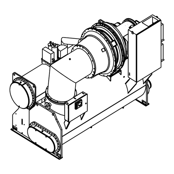
- Page 7 CVHG or 2 stage compressor on CVHF, — 2-stage economizer on CVHE, CVHG, or single economizer on CVHF, See Figure 1 for Typical CVHE and CVHG, and Figure 2 for Typical CVHF major components. Figure 1. General CVHE and CVHG unit components CVHE-SVU01E-EN...
- Page 8 General Information Figure 1. General CVHE and CVHG unit components - continued CVHE-SVU01E-EN...
- Page 9 General Information Figure 2. Illustrates the general component layout of a typical CVHF chiller CVHE-SVU01E-EN...
- Page 10 Once the gas is compressed a third time, it is discharged into the CVHE-SVU01E-EN...
- Page 11 General Information Figure 3. CVHE, CVHG pressure enthalpy curve Figure 4. CVHE, CVHG 2-stage economizer CVHE-SVU01E-EN...
- Page 12 General Information Figure 5. CVHF pressure enthalpy curve Figure 6. CVHF single stage economizer CVHE-SVU01E-EN...
- Page 13 Tracer CH530 updates. For more information on TechView ™ visit your local Trane Service company, or The Trane Company’s website at Figure 7. CVHE, CVHF, and CVHG sequence of operation overview www.trane.com. CVHE-SVU01E-EN...
- Page 14 General Information Figure 8. CVHE, CVHF, and CVHG sequence of operation: power up to starting Figure 9. CVHE, CVHF, and CVHG sequence of operation: running CVHE-SVU01E-EN...
- Page 15 General Information Figure 10. CVHE, CVHF, and CVHG sequence of operation: satisfied setpoint Figure 11. CVHE, CVHF and CVHG sequence of operation: normal shutdown to stopped and run inhibit CVHE-SVU01E-EN...
- Page 16 The connection is on the side where a weir assures a preferential supply of liquid. Refrigerant is delivered to the motor via the pump. Motor refrigerant drain lines are routed to the condenser. CVHE-SVU01E-EN...
- Page 17 General Information Figure 12. Oil refrigerant pump CVHE-SVU01E-EN...
- Page 18 The Control limit point. setpoint the current limit algorithm binary input is at 1A18 Terminals J2-1 holds against this loading command. and J2-2 (Ground) which acts as a switch closure input to enter the base-loading mode. The second CVHE-SVU01E-EN...
- Page 19 General Information Figure 13. Base loading with external mA input and with external voltage input CVHE-SVU01E-EN...
- Page 20 1. Front Panel Disable, or 2. Opening the external Ice. Contacts/ Remote communicated input (Tracer), or 3. Satisfying an evaporator entering fluid temperature setpoint (Default to 27°F). 4. Surging for 7 minutes at full open IGV. CVHE-SVU01E-EN...
- Page 21 — a refrigerant gas line, and electrically-actuated shutoff valve, between the evaporator and condenser; — a valve liquid return line, and electrically-actuated shutoff valve, between the condenser sump and the evaporator; — a liquid refrigerant storage vessel (larger economizer); and, — additional refrigerant. CVHE-SVU01E-EN...
- Page 22 FC auxiliary relay and can be used as shut down first, (Run: Unload, Post required. Lube, and drive vanes closed). After the vanes have been overdriven, closed and condenser water proven, the Free Cooling relays will be CVHE-SVU01E-EN...
- Page 23 Menus by enabling the option. The down, the inlet guide vanes will be setting the HGBP Cut-In Vane driven fully closed, and the HGBP Position is setup at unit commissioning via the service tool. CVHE-SVU01E-EN...
- Page 24 Tracer is also able to set the hot side. water setpoint. In the hot water mode the external chilled water setpoint is the external hot water setpoint; that is, a single analog input is shared at the 1A16 –J2-1 to J2-3 (ground) CVHE-SVU01E-EN...
- Page 25 Water only possible if a cooling load exists Trane does not recommend circulated through the heat-recovery to act as a heat source.) operating the auxiliary condenser (or auxiliary) condenser tube bundle alone because of its small size.
-
Page 26: Unit Control Panel (Ucp)
UCP door. (See Operators LLID’s and can be temperature interface section for detailed sensors or pressure transducers. information) These and other functional switches provide analog and binary inputs to the control system. Figure 16. Control panel and approximate dimensions CVHE-SVU01E-EN... - Page 27 This distributed logic allows intelligent response to changing the main processor to focus on responding to changing conditions — in the load, the machine, its ancillary equipment, or its power supply. Tracer CH530 constantly receives information about key data parameters, temperatures and CVHE-SVU01E-EN...
-
Page 28: Operator Interface
CVHE-SVU01E-EN... - Page 29 The advantage of touch sensitive buttons is that the full range of possible choices as well as the current choice is always in view. CVHE-SVU01E-EN...
- Page 30 The prevent an inadvertent chiller stop Auto and Stop keys will be from the DynaView screen for those presented as radio buttons within the chillers which are solely controlled persistent key display area. The by the CH530. CVHE-SVU01E-EN...
- Page 31 Preparing To Shutdown Unit is closing inlet guide vanes prior to compressor shutdown. Shutting Down Compressor has been stopped and unit is performing shutdown tasks. Free Cooling Unit is in Free Cooling mode and will not run the compressor. CVHE-SVU01E-EN...
- Page 32 Waiting For A Need To Cool Auto Waiting For A Need To Heat Auto Power Up Delay Inhibit: MIN:SEC Waiting To Start Waiting For Condenser Water Flow Waiting To Start Establishing Oil Pressure Waiting To Start Pre-Lubrication Time: MIN:SEC CVHE-SVU01E-EN...
- Page 33 Free Cooling Opening Free Cooling Valves Free Cooling Closing Free Cooling Valves Preparing To Shutdown Closing IGV: IGV Position % Shutting Down Post-Lubrication Time: MIN:SEC Shutting Down Evaporator Pump Off Delay: MIN:SEC Shutting Down Condenser Pump Off Delay: MIN:SEC CVHE-SVU01E-EN...
- Page 34 Active Hot Water Setpoint (>>source) Active Current Limit Setpoint (>>source), If enabled Active Base Loading Setpoint (>>source), If enabled Purge Operating Mode Purge Status Average Line Current Approximate Chiller Capacity, If option installed Active Ice Termination Setpoint (>>source), If option installed Software Version CVHE-SVU01E-EN...
- Page 35 Alarms enunciator. can cause a repeat failure. Contact override. An Alarm will take When an alarm is present, the alarm local Trane Service for assistance as precedence of the Manual, until the enunciator is present next to the Stop necessary.
- Page 36 BAS, and external column “- - - -” will be shown if that setpoints, option is Not Installed, otherwise the current setpoint from that source will be shown. The “Back” button provides navigation back to the chiller screen. CVHE-SVU01E-EN...
- Page 37 “Back” button provides navigation unit is currently controlling. It is the back to the chiller screen. result of arbitration between the front panel, BAS, and external setpoints. Note: This is the same for other setpoints in the “Main” menu. CVHE-SVU01E-EN...
- Page 38 Approximate Condenser Water Flow, If installed Gpm or LPM Auxiliary Condenser or Heat Recovery Entering Water Temperature, If installed °C or °F Auxiliary Condenser or Recovery Leaving Water Temperature, If installed °C or °F Outdoor Air Temperature, If installed °C or °F CVHE-SVU01E-EN...
- Page 39 Percent Pumpout Chiller On – 7 Days Percent Pumpout Chiller Off – 7 Days Percent Pumpout - Life Minute Purge Refrigerant Compressor Suction Temperature °C or °F Purge Liquid Temperature °C or °F Carbon Tank Temperature °C or °F CVHE-SVU01E-EN...
- Page 40 GPM or LPM 38. Second Condensor Entering Water Temperature, If installed °C or °F 39. Second Condensor Leaving Water Temperature, If installed °C or °F Historic Diagnostics Log 1 to 20 Historic Diagnostics (main processor software 6.0 and later) CVHE-SVU01E-EN...
-
Page 41: Chilled Water Setpoint
Settings screen for standard CTV : Chilled Water Setpoint: To change chilled water setpoint first select the settings tab screen. Chilled water setpoint is within the chiller sub-menu. (See next page for setpoint listing.) CVHE-SVU01E-EN... - Page 42 (Auto, On), Auto 1) Condenser Flow status 2) Override Time Remaining 4. Oil Pump (Auto, On), Auto 1) Differential pressure 2) Override Time Remaining 5. Purge Exhaust Circuit Test (Off, On), 6. Purge Regeneration Cycle (Off, On), Carbon Temperature CVHE-SVU01E-EN...
- Page 43 Language shall always be the last setting listed on the Display Settings menu. This will allow a user to find language selection if looking at an unrecognizable language. (7) Manual Compressor Control allows an operator to override the Auto Control and manually control the compressor while in operation. This is not active during Stop mode. CVHE-SVU01E-EN...
- Page 44 Analog setpoints are displayed as spin buttons. The lower half of the screen is reserved for help screens. To change the setpoint the ENTER key must be touched, otherwise the new setting is cancelled. Note: Spin buttons used to change setpoint value. CVHE-SVU01E-EN...
- Page 45 Settings with buttons only [screen has no cancel or enter key] do accept the new selection immediately. Note: Radio 1 and Radio 2 refer to “touch sensitive buttons.” The labels depend upon the setting being controlled. Mode Override for Enumerated Settings is shown below: CVHE-SVU01E-EN...
- Page 46 Enter or Cancel the entry. Mode Override for Analog Settings is shown below: The date setpoint screen for setting up the is shown below: The user must select Day, Month, or Year and then use the up or down arrows to adjust. CVHE-SVU01E-EN...
- Page 47 The time setpoint screen with a 12-hour format is shown below: The user must select Hour, or Minute and then use the up or down arrows to adjust. Adjusting hours will also adjust am and pm. Note: The 24-hour format setpoint screen is similar with the am and pm not shown. CVHE-SVU01E-EN...
- Page 48 MP temperature is below 32°F (0°C) and it has been 30 minutes after the last key stroke. Note: the main processor is equipped with an on-board temperature sensor which enables the ice protection feature. CVHE-SVU01E-EN...
-
Page 49: Inter Processor Communication (Ipc)
IPC3 bus network. The various commissioned, the LLIDS must have devices are discussed in the their node addresses assigned to upcoming sections. them for storage in non-volatile memory. The node addresses are normally assigned sequentially during factory commissioning. CVHE-SVU01E-EN... -
Page 50: Control System Components
Figure 20 illustrated below, present in all configurations. Other Condenser Pressure, TRMM Tracer identifies these devices. The Control Modules vary depending on machine Panel Devices table corresponds to optional devices. Figure 20. Control panel components layout and approximate dimensions CVHE-SVU01E-EN... - Page 51 Control System Components CVHE-SVU01E-EN...
- Page 52 Oil Pump Motor Branch not for field use Circuit protection 1X1 Terminal Block Standard Control Panel Terminal Block, 1X1-5 Chilled water flow Flow switch connections flow switch input 1X1-6 Condenser water flow switch input *previously was located in Purge Control Panel CVHE-SVU01E-EN...
- Page 53 Option the unit will use the Limit warning machine shutdown condenser refrigerant temperature auto reset relays will activate with sensor (input converted to saturated such conditions for remote status refrigerant pressure) to perform the indication. Standard Condenser Limit function, CVHE-SVU01E-EN...
- Page 54 J2-1 Binary Input Signal #1, Binary input module Enable or Disable input point J2-2 Ground *previously was 1A10 Refrigerant Monitor Input 1A17 Analog type input 4-20ma input signal to the 1A17 J2-4 to J2-6 (ground). This represents 0-100 ppm. CVHE-SVU01E-EN...
- Page 55 EPRO (Enhanced Protection) 4R22 EPRO Condenser Refrigerant Pressure Transducer 4R16 EPRO Compressor Discharge Refrigerant Temperature Sensor. (This is also included with H6BP). EPRO Inboard Bearing Temperature Sensor EPRO Outboard Bearing Temperature Sensor *See CTV-PRB006-EN for “Condenser Water Temperature Control”. CVHE-SVU01E-EN...
- Page 56 10.0 2 to 10 Vdc corresponds to 0 Psia to VDC. the HPC (in Psia) setting. Note: Controls allow Delta Pressure or condenser pressure output, but not both. Figure 21. Condenser pressure based output CVHE-SVU01E-EN...
- Page 57 30 psi are individually adjustable via the service tool. Note: Typical settings for CVHE, F, G with refrigerant pumps are as follows. • Min pressure 0 psid (= 2 vdc) • Max pressure 6 psid (= 10 vdc) • Target tower control at 4 psid CVHE-SVU01E-EN...
- Page 58 Example: If RLA is 500 amps then connections are on the terminals 10 vdc = 600 amps. 1A15 –J2-1 (+) to J2-3 (Ground). The Percent RLA Output is polarity sensitive. The following graph illustrates the output: Figure 23. Voltage versus percent RLA CVHE-SVU01E-EN...
- Page 59 Relay Outputs at 120 VAC: 7.2 Amps Power, 24 +/- 10 percent VDC, 20 mA resistive, 2.88 Amps pilot duty, 1/3 maximum. Trane IPC3 protocol. J1-1 1A1, 1A2 Power Supply : HP , 7.2 FLA at 240 VAC: 5 Amps...
- Page 60 14 AWG Relay #4 J2-10 NO, J2-11 NC, J2-12 common Power, 24 +/- 10 percent VDC, 40 mA maximum Trane IPC3 protocol. Relay Outputs: at 120 VAC: 7.2 Amps resistive, 2.88 Amps pilot duty, 1/3 1A14 Communication interface HP , 7.2 FLA, at 240 VAC: 5 Amps...
- Page 61 J2: 14 - 26 AWG with a maximum of two 14 AWG J2-2 Input #1 to J2-3 (Ground). J2-5 Input #2 to J2-6 (Ground). Power, 24 +/- 10 percent VDC, 60 mA maximum, Trane IPC3 protocol. CVHE-SVU01E-EN...
- Page 62 Unit mounted devices Probe Operating Temperature Range - EarthWise ™ Purge 40 to 250°F (-40 to 121 Trane has also revolutionized its Vane Actuator Control Accuracy +/- 0.25 C over the range -4 controller-integrated purge, which The Stepper Module within the to 122°F (-20 to 50...
-
Page 63: Controls Sequence Of Operation
From this point, circuits. 4 minutes 15 seconds minutes for the control voltage flows to: 5. The DynaView ™ display module compressor start sequence to be 1A22, receives 24 vdc power from initiated. the IPC bus. CVHE-SVU01E-EN... - Page 64 - one second. If opened through the opening of relay currents are detected the MMR 2A1-J4 100 msec after the closure of diagnostic ‘‘Starter Fault Type II’’ is the transition relay 2A1-J2, and the generated. (Starter Integrity test) run relay 2A1-J6. CVHE-SVU01E-EN...
- Page 65 ‘‘differential to temperature preparing for the next the compressor motor is immediately stop’’ setpoint, a normal chiller stop compressor motor start based on turned off. sequence is initiated as follows: the ‘‘differential to start’’ setpoint. (Refer to Figure 10.) CVHE-SVU01E-EN...
- Page 66 K. (Open S (Shorting) Contactor) milliseconds 260 milliseconds L. (Close 2M (2K2) Contactor 140 milliseconds M. (Wait to look for Transition complete) milliseconds 2.32 to 2.38 second N. (Filtering time on Transition complete input) milliseconds 160 to 240 milliseconds CVHE-SVU01E-EN...
- Page 67 (4K8), Maximum Acceleration Timer Setting by Starter Type Wye-Delta 27 Seconds Auto-Transformer Primary Reactor Across the Line Solid State CVHE-SVU01E-EN...
-
Page 68: Machine Protection And Adaptive Control
Power interruptions of less reconnecting the compressor motor than 30 line-cycles are defined as ™ Figure 25. CVHE, CVHF, and CVHG sequence of operation: momentary power loss, (DynaView and Starter module remain powered) CVHE-SVU01E-EN... - Page 69 The linear time-trip curve is as displayed. follows: Figure 26. Overload trip time versus percent RLA The Maximum Acceleration Time Setting and Current Transformer Setting are factory set however can be set with the service tool; CVHE-SVU01E-EN...
- Page 70 -Diagnostic cleared when the average to Enable, however can be disabled stable control if the Current Limit of the three line voltages is 90% or via the service tool. setpoint is adjusted during a run. greater of the unit line voltage set point. CVHE-SVU01E-EN...
- Page 71 If it necessary to change from the and maximum (default at 100 percent) is not able to unload quickly enough, defaults. capacity are adjustable via the service the supply water temperature will tool. CVHE-SVU01E-EN...
- Page 72 Evaporator diagnostic. adjustable from the chilled water refrigerant temperatures. This limit setpoint and factory set. Shutdown of allows the chiller to continue to run the compressor due to violation of at a reduced load. the Leaving Water Temperature CVHE-SVU01E-EN...
- Page 73 5°F below the cutout setting. TechView programmable head relief High Evaporator Water Temperature relay filter times setpoint. The default Cutout is a setpoint that is adjustable is one minute. in TechView from 80°F and 150°F. The default is 105°F. CVHE-SVU01E-EN...
- Page 74 Unload: The potential to unload increases as the saturated evaporator temperature falls further below the evaporator limit setpoint. Figure 27 illustrates these functions as follows: • chilled water setpoint • evap leaving water temp cutout • evap rfgt temp output CVHE-SVU01E-EN...
- Page 75 (VPF) water- flow, variable flow compensation allows the chiller to respond quickly to accelerating or decelerating water. By automatically adjusting the control gain, large changes in the water-flow rate can be tolerated. For details, refer to CTV-PRC007-EN. CVHE-SVU01E-EN...
- Page 76 3 free starts. compressor and operate remaining will be displayed along independently of other compressors with the restart inhibit mode. on that chiller. CVHE-SVU01E-EN...
- Page 77 100°F/37.8°C or the Saturated Evaporator Refrigerant Temperature + 30°F/16.7°C. If the Enhanced Oil Temperature Protection setting is not enabled, the Low Oil Temperature Start Inhibit value is settable with the Low Oil Temperature Start Inhibit Setpoint via the service tool. CVHE-SVU01E-EN...
- Page 78 60 consecutive seconds this diagnostic is issued. High Oil Temperature Cutout Name: High Oil Temperature Cutout Type of Diagnostic: Latching, results in Immediate Shutdown. Default Setpoint value: 180°F (82.2°C) Implemented to avoid overheating of the oil and the bearings. CVHE-SVU01E-EN...
- Page 79 Reset Setpoint, and the Maximum reference. The MAXIMUM RESET = Design Reset Setpoint. TOD is the Temperature Outdoor Delta Temperature Sensor. The equation for Constant Return is TWE is entering evaporator water as follows: temperature. TWL is the Leaving Evaporator Temperature. CVHE-SVU01E-EN...
- Page 80 Degrees of Reset: Degrees of Reset = Active CWS - Front Panel CWS Degrees of Reset = CWS’ - CWS To obtain Active CWS from Degrees of Reset: Active CWS = Degrees of Reset + Front Panel CWS (* = multiply) CVHE-SVU01E-EN...
- Page 81 .5 in the equation Degrees of Reset = Reset Ratio*(Start (* = multiply) Reset - TOD) TOD = Outdoor Air Temperature Degrees of Reset = .35*(80-65) Degrees of Reset = 5.25 Figure 28. Outdoor air temperature versus degrees of reset CVHE-SVU01E-EN...
- Page 82 Machine Protection and Adaptive Control Figure 29. Reset function for return CWR Figure 30. Reset function for return CWR Note: This graph assumes Maximum Reset is set to 20 degrees. CVHE-SVU01E-EN...
- Page 83 Degrees of Reset = .7*(20-(60-53)) Degrees of Reset = 9.1 TWL = 45 Degrees of Reset = 2.5 Maximum Reset = 8 Reset Ratio = 70% Start Reset = 20 TWE = 60 TWL = 53 Maximum Reset = 14 CVHE-SVU01E-EN...
- Page 84 Machine Protection and Adaptive Control Figure 31. Return CWR Figure 32. Constant CWR CVHE-SVU01E-EN...
-
Page 85: Unit Startup
Oil pressure must be verified within 3 Chiller Settings menu. minutes or a MMR diagnostic is generated. 6. If necessary, readjust the current limit setpoint in the Chiller Setpoints menu. 7. Press “AUTO”. CVHE-SVU01E-EN... - Page 86 Should a rupture disk fail, evacuate the area immediately and contact the appropriate rescue or response authority. Failure to take appropriate precautions or react properly to a potential hazard could result in death or serious injury. CVHE-SVU01E-EN...
-
Page 87: Unit Shutdown
Unit Shutdown Unit Shutdown Procedures manual should be performed by qualified Trane service technicians. Daily Unit Shutdown Note: During extended shutdown, be Note: Refer to Start-Run Shutdown sure to operate the purge unit for a 2- sequence in General Information hour period every two weeks. -
Page 88: Periodic Maintenance
(fouled the latest revision which can be [ ] Check the oil level in the chiller oil condenser tubes, noncondensable in obtained at the nearest Trane office. sump using the two sight glasses the system, etcetera) Record Keeping Forms provided in the oil sump head. - Page 89 For variable frequency weekly maintenance procedures. drives or other energy storing Refer to the previous sections for components provided by Trane or details. others, refer to the appropriate manufacturer’s literature for [ ] Clean all water strainers in the allowable waiting periods for CenTraVac water piping system.
-
Page 90: Annual Maintenance
Shut down the chiller once each year refrigerant temperature displayed on and adding several drops of Trane to check the items listed ; a more the UCP’s read-out is outside this 4- OIL00022. Replace plug. -
Page 91: Oil Maintenance
Forcing the oil from the oil sump by Note: Use only Trane OIL00022. A full rather than automatically change the pressurizing the chiller (by raising oil change is 9 gallons of OIL00022. - Page 92 The chiller is now ready valve with wrench flats to allow for operation. turning. The spring force on the locking pin should allow the pin to 7. Purge unit. drop into a detent at this position. 8. Check oil pressure 18-27 psi. CVHE-SVU01E-EN...
-
Page 93: Maintenance
For variable frequency [ ] Submit a sample of the 6. Using a grease gun with an drives or other energy storing compressor oil to a Trane qualified appropriate fitting, insert ONLY components provided by Trane or laboratory for comprehensive... - Page 94 Grease fittings are not actuators from the tang operator few drops of Trane OIL00022 in the vacuum-tight and will become a leak arms in order to test for a cavity. Be sure to reinstall the pipe path.
- Page 95 The available pressure Note: If your chiller is covered by a and may be under positive pressure. differential. Trane extended warranty, the terms of Recover refrigerant to relieve c. Gravity. (Use a return vent line that warranty may require that the pressure before opening the system.
- Page 96 To leak-test a chiller containing full determine what water treatment, if refrigerant charge, raise chiller any, is required. Trane assumes no pressure using a controlled hot water responsibility for equipment failures or electric-resistance system to a which result from untreated or maximum of 8 psig.
- Page 97 Failure to follow proper procedures For control calibration and check-out, from smooth-bore tubes. could result in corrosion damage to contact a Trane qualified service To clean other types of tubes the unit and tubes. organization. including internally-enhanced types,...
- Page 98 System contains oil and refrigerant engineer that handled the order. and may be under positive pressure. The Trane EarthWise Purge is the Recover refrigerant to relieve 4. The refrigerant charge should be only purge system available for the pressure before opening the system.
- Page 99 UNTREATED OR IMPROPERLY evident, the oil must be replaced. drives or other energy storing TREATED WATER, OR EQUIPMENT components provided by Trane or DAMAGE MAY OCCUR. 12. If the unit is stored for more than others, refer to the appropriate...
-
Page 100: Forms
CVHE-SVU01E-EN... - Page 101 CVHE-SVU01E-EN...
- Page 102 CVHE-SVU01E-EN...
- Page 103 CVHE-SVU01E-EN...
- Page 104 CVHE-SVU01E-EN...
- Page 105 CVHE-SVU01E-EN...
- Page 106 CVHE-SVU01E-EN...
- Page 107 CVHE-SVU01E-EN...
- Page 108 CVHE-SVU01E-EN...
- Page 109 CVHE-SVU01E-EN...
- Page 110 CVHE-SVU01E-EN...
- Page 111 CVHE-SVU01E-EN...
- Page 112 CVHE-SVU01D-EN 604 Stocking Location La Crosse Trane Trane has a policy of continuous product and product data improvement and reserves the right to change design A business of American Standard Companies and specifications without notice. www.trane.com For more information contact your local district office Only qualified technicians should perform the installation and servicing of equipment referred to in this or e-mail us at comfort@trane.com...
Need help?
Do you have a question about the CVHE-SVU01E-EN and is the answer not in the manual?
Questions and answers