Table of Contents
Advertisement
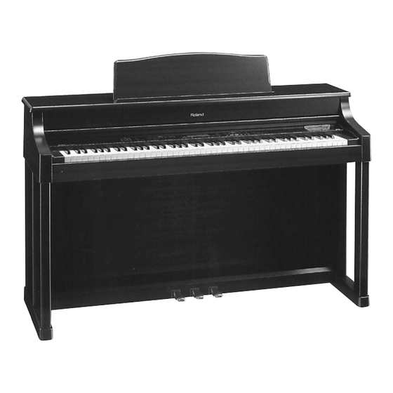
HP-555G
HP-555G
ROLAND PIANO DIGITAL
TABLE OF CONTENTS
GENERAL VIEW
PANEL LAYOUT
PANEL LAYOUT PARTS LIST
SPECIFICATIONS
EXPLODED VIEW
PARTS LIST OF EXPLODED
PARTS LIST
CHECKING THE VERSION NUMBER
HOW TO UPDATE THE FLASH MEMORY
TEST MODE
STAND ASSEMBLY
STAND EXPLODED VIEW
STAND PARTS LIST
STAND EXPLODED VIEW
STAND PARTSLIST
REPLACING FDD
PEDAL UNIT EXPLODED VIEW
CONNECT BOARD PARTS LIST
CONNECT BOARD CIRCUIT DIAGRAM
KEYBOARD DISASSEMBLY
KEYBOARD PARTS LIST
KEYBOARD PA-4A88-C2 CIRCUIT BOARD
KEYBOARD PA-4A88-C2 CIRCUIT DIAGRAM
BLOCK DIAGRAM
CIRCUIT BOARD (MAIN)
CIRCUIT DIAGRAM (MAIN)
CIRCUIT BOARD (PANEL L)
CIRCUIT BOARD (PANEL R)
CIRCUIT DIAGRAM (PANEL L / PANEL R)
CIRCUIT BOARD (FRONT JACK, ANALOG ,INLET)
CIRCUIT DIAGRAM (FRONT JACK, ANALOG ,INLET)
CIRCUIT BOARD (MIC)
CIRCUIT BOARD (LCD B)
CIRCUIT DIAGRAM (MIC)
CIRCUIT DIAGRAM (LCD B)
GENERAL VIEW
Copyright © 1998 by ROLAND CORPORATION
All rights reserved. No part of this publication may be reproduced in any form without the written permission of ROLAND CORPORATION.
17059916
SERVICE NOTES
First Edition
Issued by RJA
Page
........................................................................................................... 1
........................................................................................................... 1
........................................................................................................... 1
........................................................................................................... 2
........................................................................................................... 3
........................................................................................................... 4
........................................................................................................... 4
........................................................................................................... 8
........................................................................................................... 8
........................................................................................................... 9
........................................................................................................... 15
........................................................................................................... 17
........................................................................................................... 18
........................................................................................................... 19
........................................................................................................... 20
........................................................................................................... 20
........................................................................................................... 21
........................................................................................................... 21
........................................................................................................... 21
........................................................................................................... 22
........................................................................................................... 23
........................................................................................................... 23
........................................................................................................... 24
........................................................................................................... 25
........................................................................................................... 26
........................................................................................................... 27
........................................................................................................... 28
........................................................................................................... 29
........................................................................................................... 30
........................................................................................................... 31
........................................................................................................... 32
........................................................................................................... 33
........................................................................................................... 33
........................................................................................................... 34
........................................................................................................... 34
Printed in Japan AA00 (DP) 1
PANEL LAYOUT
FRONT VIEW
p
q
w
e
r
t
Balance
Accomp
Keyboard
Function
Brilliance
Mellow
Bright
Volume
Reverb
Chorus
Min
Max
y
o
!0
!1
Metronome
Song
Beat
Tempo
Exit
t
!3
t
Count In
Marker
Clear
A
B
Repeat
!4
u
PANEL LAYOUT PARTS LIST
No.
Pno.
Part Name
p
00671556
SLIDE POT. EWANNKX10B14
q
00346178
SLIDE POT. RS30111CA
w
22485192
I S-KNOB S BLK/LCG
e
22245194
POT DUST COVER M 1H
r
32225353
I S-ESCT SX1V BLK L=30
t
00900145
D S-KEYTOP SD1H BLK
y
00900156
D S-KEYTOP SD2H BLK
u
00900167
D S-KEYTOP SD3H BLK
i
00900178
D S-KEYTOP SD4H BLK
o
01346390
HP-535 ISOLATOR LED SPONGE
!0
01121689
LED SPR-325MVWT31
i
Tone
Piano
E.Piano
Harpsi
Vibes
Organ
Strings
Choir GS Tones
Pianist
Split
Key Touch
Lower
u
!2
!4
u
y
Composer
Rhythm
1
2
3
4
Value
Transpose
Reset
Stop
Play
Rec
Bwd
Enter
t
!4
!5 !6 !7
!9
@0
No.
Pno.
Part Name
!1
71013990
LCD UNIT
!2
01346201
HP-535 DISPLAY COVER
!3
01125901
D S-KEYTOP SX1H-A BLK
!4
00900189
D S-KEYTOP SX1H BLK
!5
22495340
D S-KEYTOP MX1H DWG
!6
22495312
D S-KEYTOP MD1H MCG
!7
01013023
D S-KEYTOP SD1H DRD
!8
00900190
D S-KEYTOP SX2H BLK
!9
01341956
FDD MF355F-3252MG
@0
01011923
ESCUTCHEON FDD
Nov. 1998
!4
t
Disk
Menu
Fwd
!8
1
Advertisement
Table of Contents

Related Manuals for Roland HP-555G


Summary of Contents for Roland HP-555G
- Page 1 FDD MF355F-3252MG 01346390 HP-535 ISOLATOR LED SPONGE 01011923 ESCUTCHEON FDD All rights reserved. No part of this publication may be reproduced in any form without the written permission of ROLAND CORPORATION. 01121689 LED SPR-325MVWT31 17059916 Printed in Japan AA00 (DP) 1...
-
Page 2: Specifications
HP-555G Nov. 1998 SPECIFICATIONS HP-555G :ROLAND DIGITAL PIANO <Disk Drive / Disk Storage> <Keyboard> Keyboard 3.5 inch Micro Floppy Disk Drive :88 keys Hammer action mechanism Disk Format TouchSensitivity :720K byte (2DD) / 1.44M byte (2HD) :Preset:3 Levels, User Programs:60 levels... -
Page 3: Exploded View
HP-555G Nov. 1998 EXPLODED VIEW NOTE The cushion under the UPPER BLIND H is #01452501 UPPER BLIND CUSHION. -
Page 4: Parts List Of Exploded
SIDE PANEL R ASSY 00341778 KEY FELT 01455778 END BLOCK R 01346201 DISPLAY COVER 71011901 MIC BOARD ASSY 00890990 ROLAND BADGE 12 GOLD 01349778 FULL-RANGE PD-20103A3 01455767 END BLOCK L 00904145 TW HOLDER 01455778 END BLOCK R 00904090 TWEETER TW-5104A... - Page 5 HP-555G Nov. 1998 00900467 PWB HOLDER NOTE1: PANEL L BOARD ASSY includes the following parts. 22245194 POT DUST COVER M 1H 22145199 SHAFT STAY L 01450034 WIRING 12X400-P2.0-51065-51015-F 22145901 SHAFT STAY R 01450045 WIRING 8X400-P2.0-51065-51015-F 01234656 HINGE CUSHION A 01450023 WIRING 9X350-P2.0-51065-51015-F...
- Page 6 HP-555G Nov. 1998 71011867 PAB3 FRONT JACK BRD 15019444 MTZJ T-77 9.1B ZENER D17,20,21 on PAB NOTE : PAB3 FRONT JACK BOARD includes the following parts. 15039159T0 S5688G(TPA3) RECTIFIER D3,4,9,10,11,13,14,19 on PAB OPTICAL DEVICE 01344545 JACK HOLDER 01346489 LED LNJ308G8LRA...
- Page 7 HP-555G Nov. 1998 13369564 B12B-PH-K-S CONNECTOR CN11 on MB ACCESSORIES 13369898 B2P3-VH 7A/250V CONNECTOR CN402 on IB 71121034 OWNER’S MANUAL ENGLISH 13369585 B3P5-VH 7A/250V CONNECTOR CN401 on IB 71012667 OWNER’S MANUAL JAPANESE 13369567 B4B-PH-K-S CONNECTOR CN4 on PAB 13499219 AC CORD SET 100V...
-
Page 8: Checking The Version Number
NUMBER MEMORY Press the [Function] button to enter Function mode. HP-555G uses Flash Memory for the main program registration, Then while holding down the [PLAY] and [TRACK[4]] buttons, you can make the software update by floppy disks via internal FDD. -
Page 9: Test Mode
HP-555G Nov. 1998 TEST MODE Note!: When you enter item 9), the user setting data will be set to the factory settings. Required Items • MIDI Cable (1.5m or longer Part No.23485229 1.5m) • Computer Test Cable for Sound Canbas SC-88 (P/No. 17049906) •... - Page 10 HP-555G Nov. 1998 If a problem is found, the following error display will appear. DEVICE (Error content) Err PROGRAM ROM Program (Flush or mask ROM) fault Err DRAM Work DRAM read/write fault Err Wave ROM Wave ROM data content fault...
- Page 11 HP-555G Nov. 1998 Press the following button twice, and confirm that a sound is heard and that the button LED on the left side of the display changes from orange to green to dark, and that the button LED goes dark the second time.
- Page 12 HP-555G Nov. 1998 INDICATION of LCD Names of the pedals SS*(value) Soft Pedal SF*(value) Sostenute DP*(value) Damper BL (value) Balance Slider If no problem is found, you will automatically advance to the following item. 6. Serial interface check When you want to go to the next test item during this check, press [Function] button.
- Page 13 HP-555G Nov. 1998 (2) PC1: Settings for connection to a PC-9800. Set the computer switch to PC1. An underline will be displayed below P1 in the LCD. Connect a computer test cable (part no. 17049906) to the Computer connector under the keyboard, and turn on the switch of the computer test cable.
- Page 14 Now press the [Beat] button to select DOM (100V) specifications, or press the [Tempo] button to select EXP (117/230/240V) specifications. * When you enter this setting, the HP-555G will automatically return to the factory settings. Press [Function] button to proceed to the next test.
-
Page 15: Stand Assembly
HP-555G Nov. 1998 2. Fixing the Pedal Board and Side Boards STAND ASSEMBLY (KS-505) ¡ Position the Pedal Board so it rests on top of the metal fitting at the bottom of the Side Board q. 1. Part Check Before you begin assembling the stand, check that all the parts were supplied. - Page 16 HP-555G Nov. 1998 3. Fitting the Rear Board 5. Connecting the Pedal and Power Cords ¡ Position the Rear Board so the side on which the wood- ¡ Connect the pedal cord to the Pedal jack on the rear of the grain is visible faces the same direction as the three piano.
-
Page 17: Stand Exploded View
HP-555G Nov. 1998 STAND EXPLODED VIEW STAND EXPLODED VIEW 71019545 SIDE BOARD L ASSY 117/230/240V ONLY 71120045 PEDAL BOARD ASSY 117/230/240V ONLY (71019556 SIDE BOARD R ASSY) 71019823 PEDAL UNIT Pno. Part Name 71120045 PEDAL BOARD ASSY 22245308 PEDAL BOARD FELT... -
Page 18: Stand Parts List
HP-555G Nov. 1998 STAND PARTS LIST Parts No. Description 71019923 KS-505/KS-505D SCREW SET 01451867 REAR BOARD NOTE : SCREW SET includes the following parts. 71019556 SIDE BOARD R ASSY NOTE : SIDE BOARD R ASSY includes the following parts. 40010589 5 x 20mm TRASS HEAD FeBZC ×... -
Page 19: Stand Exploded View
HP-555G Nov. 1998 STAND EXPLODED VIEW STAND EXPLODED VIEW 71018878 SIDE PANEL L ASSY 100V ONLY 71120045 PEDAL BOARD ASSY 100V ONLY (71018889 SIDE PANEL R ASSY) 71019823 PEDAL UNIT The items bracketed by( )are parts for SIDE PANEL ASSY R Pno. -
Page 20: Stand Partslist
(PNo.40122612) (10mm wide) to the new FDD before 71018889 SIDE BOARD R ASSY mounting it on HP-555G (see the figure below). 5 × 20mm TRASS HEAD FeBZC ×2 NOTE : SIDE BOARD R ASSY includes the following parts. 40010589 4 ×... -
Page 21: Pedal Unit Exploded View
HP-555G Nov. 1998 PEDAL UNIT EXPLODED VIEW CONNECT BOARD PARTS LIST 15229728 GP2S24B PHOTO INTERRUPTER 15119112 2SA1015Y TRANSISTOR 13299199 EVND8AA03B13 TRIMMER CONNECT BOARD CIRCUIT DIAGRAM PARTS LIST Parts No. Part Name 71018623 PEDAL CENTER 00904190 PEDAL CHASSIS 00908023 FELT L... -
Page 22: Keyboard Disassembly
HP-555G Nov. 1998 Installing the PA-4A board KEYBOARD DISASSEMBLY As shown in Fig.3, place the board against the hook part a of the sub-shassis, and screw the board into the sub-shassis. Removing PA-4A key Screw in order, from the round hole(positioning hole) on the While holding the front end of the key, insert the tip of long-nose connector side. -
Page 23: Keyboard Parts List
HP-555G Nov. 1998 KEYBOARD PARTS LIST KEYBOARD PA-4A88-C2 CIRCUIT BOARD/ HP-335/535/245/555G·KR-575/575P PA-4A88-C2 KEYBOARD ASSY PARTS LIST 71017401 PARTS No. Qty. PARTS NAME 00455501 PA-4A N-KEY A 00455512 PA-4A N-KEY B 00455534 PA-4A N-KEY C 00455545 PA-4A N-KEY D 00455556 PA-4A... -
Page 24: Keyboard Pa-4A88-C2 Circuit Diagram
HP-555G Nov. 1998 KEYBOARD PA-4A88-C2 CIRCUIT DIAGRAM... -
Page 25: Block Diagram
HP-555G Nov. 1998 BLOCK DIAGRAM... -
Page 26: Circuit Board (Main)
HP-555G Nov. 1998 CIRCUIT BOARD (MAIN) ASSY 71012690 View from components side. View from foil side. -
Page 27: Circuit Diagram (Main)
HP-555G Nov. 1998 CIRCUIT DIAGRAM (MAIN) -
Page 28: Circuit Board (Panel L)
HP-555G Nov. 1998 CIRCUIT BOARD (PANEL L) ASSY 71012712 NOTE PANEL L BOARD ASSY includes the following parts. 01450034 12X400-P2.0-51065-51015-F WIRING 01450045 8X400-P2.0-51065-51015-F WIRING 01450023 9X350-P2.0-51065-51015-F WIRING View from components side. -
Page 29: Circuit Board (Panel R)
HP-555G Nov. 1998 CIRCUIT BOARD (PANEL R) ASSY 71012723 NOTE PANEL R BOARD ASSY includes the following parts. 01452712 10X100-P2.0-51065-51015-F WIRING 01452734 14X350-P2.0-51065-51015-F WIRING 01452723 15X400-P2.0-51065-51015-F WIRING View from components side. -
Page 30: Circuit Diagram (Panel L / Panel R)
HP-555G Nov. 1998 CIRCUIT DIAGRAM (PANEL L / PANEL R) -
Page 31: Circuit Board (Front Jack, Analog ,Inlet)
HP-555G Nov. 1998 CIRCUIT BOARD (FRONT JACK, ANALOG ,INLET) NOTE PAB3 ANALOG PHANTOM includes the following parts. 71011878 PAB3 INLET 100/117V 71011867 FRONT JACK BOARD ******** PAB3 EQ BOARD ASSY ******** PAB3 ANALOG BOARD NOTE : PAB3 ANALOG BOARD includes the following parts. -
Page 32: Circuit Diagram (Front Jack, Analog ,Inlet)
HP-555G Nov. 1998 CIRCUIT DIAGRAM (FRONT JACK, ANALOG ,INLET) HP-535/555G EQ BOARD ASSY 71011978 PAB3 C212 C206 PANEL L EQUALIZER 0.082 BOARD BOARD BOARD 0.068 (CN1) (CN1) (CN201) 3.3/50 R208 R217 R212 C208 53253-0810 53253-0610 B10B-XH-A 6.8K C204 6.8K 0.082... -
Page 33: Circuit Board (Mic)
HP-555G Nov. 1998 CIRCUIT BOARD (MIC) ASSY 71011901 NOTE MIC BOARD ASSY includes the following parts. 22150756 JACK NUT 2 01344489 MIC HOLDER View from components side. CIRCUIT BOARD (LCD B) ASSY 71012167 View from components side. -
Page 34: Circuit Diagram (Mic)
HP-555G Nov. 1998 CIRCUIT DIAGRAM (MIC) CIRCUIT DIAGRAM (LCD B)
Need help?
Do you have a question about the HP-555G and is the answer not in the manual?
Questions and answers