
Related Manuals for Yamaha GRIZZLY 660 YFM66FGX


Summary of Contents for Yamaha GRIZZLY 660 YFM66FGX
- Page 1 OWNER’S MANUAL MANUEL DU PROPRIÉTAIRE MANUAL DEL PROPIETARIO YFM66FGX 23D-28199-60...
- Page 2 YAMAHA MOTOR CO., LTD. PRINTED ON RECYCLED PAPER PRINTED IN JAPAN IMPRIMÉ SUR PAPIER RECYCLÉ 2007.03-0.3×1 CR IMPRESO EN PAPEL RECICLADO (E,F,S)
- Page 3 OWNER’S MANUAL YFM66FGX 23D-28199-60-E0...
-
Page 4: Ec Declaration Of Conformity
Directive 98/37/EC YAMAHA MOTOR EUROPE N.V., (Name of supplier) Koolhovenlaan 101, 1119 NC Schiphol-Rijk, The Netherlands, representing YAMAHA MOTOR CO., LTD., Iwata, Japan, declare in sole responsibility, that the product YFM660FWA (JY4AM03W050000001~) (Make, model) to which this declaration applies, conforms to the essential... - Page 5 Yamaha experience in the production of fine sporting, touring, and pacesetting racing machines. With the purchase of this Yamaha, you can now appreciate the high degree of craftsmanship and reliability that have made Yamaha a leader in these fields.
- Page 6 EBU17330 IMPORTANT MANUAL INFORMATION EBU17341 FAILURE TO FOLLOW THE WARNINGS CONTAINED IN THIS MANUAL CAN RESULT IN SERIOUS IN- JURY OR DEATH. Particularly important information is distinguished in this manual by the following notations: The Safety Alert Symbol means ATTENTION! BECOME ALERT! YOUR SAFETY IS INVOLVED! Failure to follow WARNING instructions could result in severe injury or death to the ATV operator, a bystander, or a person inspecting or...
- Page 7 IMPORTANT NOTICE EBU17370 Welcome to the Yamaha world of motor sports! This ATV is designed and manufactured for use on UNPAVED surfaces only. It is unsafe to operate this ATV on any paved surface, paved street, paved road or motorway.
-
Page 8: Table Of Contents
EBU17420 TABLE OF CONTENTS SAFETY INFORMATION ......1-1 Fuel cock ..........4-16 Starter (choke) ..........4-17 LOCATION OF THE WARNING AND Seat ............4-18 SPECIFICATION LABELS ......2-1 Storage compartment .......4-19 Front carrier ..........4-20 DESCRIPTION ..........3-1 Rear carrier ..........4-20 Left view ............3-1 Adjusting the front and Right view............ - Page 9 OPERATION ..........6-1 PERIODIC MAINTENANCE AND Starting a cold engine ........ 6-1 MINOR REPAIR ..........8-1 Starting a warm engine ......6-3 Owner’s manual and tool kit .......8-1 Operating the drive select lever and Periodic maintenance chart for driving in reverse ........6-3 the emission control system .....8-3 Engine break-in ..........
- Page 10 Adjusting the rear brake lever free play SPECIFICATIONS ........10-1 and checking the brake pedal position ... 8-42 Axle boots ..........8-44 CONSUMER INFORMATION.......11-1 Brake light switches ......... 8-44 Identification numbers .......11-1 Checking and lubricating the cables ..8-45 Checking and lubricating the front and rear brake levers ....
-
Page 11: Safety Information
EBU17430 SAFETY INFORMATION EBU17502 Never carry a passenger on an ATV. Always avoid operating an ATV on any paved AN ATV IS NOT A TOY AND CAN BE HAZARD- surfaces, including sidewalks, driveways, park- OUS TO OPERATE. ing lots and paved streets. An ATV handles differently from other vehicles, in- Never operate an ATV on any paved street, cluding motorcycles and cars. - Page 12 Always inspect your ATV each time you use it to Always follow proper procedures for climbing make sure it is in safe operating condition. Al- hills as described in this manual. Check the ter- ways follow the inspection and maintenance rain carefully before you start up any hill.
- Page 13 steady speed when climbing a hill. If you stall or Always be sure there are no obstacles or people roll backwards, follow the special procedure for behind you when you operate in reverse. When braking described in this manual. Dismount on it is safe to proceed in reverse, go slowly.
- Page 14 nition such as the pilot lights of water heat- EWB00070 WARNING ers and clothes dryers. Gasoline can catch fire and you could be burned. Always operate your ATV in an area with ade- When transporting the ATV in another vehi- quate ventilation.
-
Page 15: Location Of The Warning And Specification Labels
EBU17660 LOCATION OF THE WARNING AND SPECIFICATION LABELS... - Page 16 Read and understand all of the labels on your ATV. These labels contain important information for safe and proper operation. Never remove any labels from your ATV. If a label becomes difficult to read or comes off, request a replace- ment label from your Yamaha dealer. For Europe and Oceania...
- Page 17 For Europe...
- Page 18 For Europe...
- Page 19 For Europe...
- Page 20 For Oceania...
- Page 21 For Oceania...
-
Page 22: Description
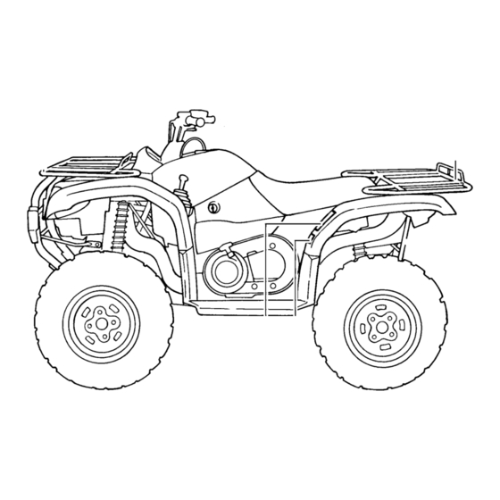
EBU17680 DESCRIPTION EBU17690 EBU17700 Left view Right view 1. Radiator cap 1. Rear shock absorber assembly spring preload adjusting ring 2. Fuel tank cap 2. Spark arrester 3. Fuel cock 3. Storage compartment and tool kit 4. Oil filter cartridge 4. -
Page 23: Controls And Instruments
EBU17712 NOTE: Controls and instruments The ATV you have purchased may differ slightly from the figures shown in this manual. 1. Drive select lever 2. Rear brake lever 3. Handlebar switches 4. Horn switch 5. Starter (choke) 6. Multifunction display 7. -
Page 24: Instrument And Control Functions
EBU17731 INSTRUMENT AND CONTROL FUNCTIONS EBU17760 Main switch The positions of the main switch are as follows: All electrical systems are supplied with power. The headlights and taillight come on when the light switch is on, and the engine can be started. The key cannot be removed. -
Page 25: Indicator Lights And Warning Light
10 seconds or more. NOTE: If the indicator light flashes under any other circum- stances or the speedometer does not show the speed while riding, have a Yamaha dealer check the speed sensor circuit. EBU17860 Neutral indicator light “... - Page 26 Start the engine after making sure that the EBU17970 Park indicator light “ ” warning light is out. Continuous use while This indicator light comes on when the transmis- the warning light is on may cause damage to sion is in the park position. the engine.
-
Page 27: Multifunction Display
EBU18040 two tripmeters (which show the distance trav- Multifunction display eled since they were last set to zero) a clock an hour meter (which shows the total time the key has been turned to “ON”) a fuel meter Odometer and tripmeter modes Pushing the “TRIP/ODO”... - Page 28 Clock mode Pushing the “ ”/“ ” button switches the display between the clock mode “CLOCK” and the hour meter mode “HOUR” in the following order: CLOCK → HOUR → CLOCK To set the clock 1. Set the display to the clock mode. 2.
-
Page 29: Handlebar Switches
EBU18061 EBU18100 Handlebar switches Start switch “ ” Push this switch to crank the engine with the start- ECB00050 CAUTION: See the starting instructions on page 6-1 prior to starting the engine. EBU18151 Light switch “ /OFF” Set this switch to “ ”... - Page 30 Top speed is normally limited when operating in indicate a malfunction in the electrical system. In differential gear lock. If conditions require more en- this case, take the ATV to a Yamaha dealer at the gine power when riding forward, push and hold this first opportunity.
- Page 31 es with the riding speed. You may lose control and have an accident if you cannot make a sharp enough turn for the speed you are trav- eling. EBU26603 On-Command four-wheel-drive switch “2WD”/“4WD” This ATV is equipped with a switch to change from two-wheel drive to four-wheel drive and vice-versa.
- Page 32 EBU18252 To lock the differential gear in four-wheel drive, On-Command differential gear lock switch make sure the On-Command four-wheel-drive “4WD”/“LOCK” switch is pushed in to the “4WD” position. This ATV is equipped with a switch allowing you to lock the differential gear when in four-wheel drive. Select the appropriate switch position according to the terrain and the conditions.
- Page 33 pectedly. This could distract the operator and increase the risk of losing control and causing an accident. EWB00140 WARNING Always ride at a slow speed when the ATV is in differential gear lock, and allow extra time and distance for maneuvers. All wheels turn at the same speed when the dif- ferential gear is locked, so it takes more effort to turn the ATV.
-
Page 34: Throttle Lever
This could cause an accident. Check the op- the throttle lever. eration of the throttle lever before you start the engine. If the throttle does not work smoothly, check for the cause. Correct the problem be- fore riding the ATV or consult a Yamaha dealer. 4-11... -
Page 35: Speed Limiter
EBU18321 3. Tighten the locknut. Speed limiter EWB00240 Your ATV was delivered with an adjustable speed WARNING limiter. The speed limiter keeps the throttle from Improper adjustment of the speed limiter and fully opening, even when the throttle lever is throttle could cause throttle cable damage or pushed to the maximum. -
Page 36: Brake Pedal And Rear Brake Lever
1. Front brake lever 1. Brake pedal EBU18442 Brake pedal and rear brake lever The brake pedal is located on the right side of the ATV and the rear brake lever is located on the left handlebar. To apply the rear brake, push down on the brake pedal or pull the brake lever toward the handlebar grip. -
Page 37: Drive Select Lever
EBU18611 Drive select lever The drive select lever is used to shift your ATV into the low-range, high-range, neutral, reverse and park positions. See the “Operating the drive select lever and driving in reverse” section on page 6-3 for the drive select lever operation. 1. -
Page 38: Fuel
1. Fuel tank cap 1. Fuel level 2. Fuel tank filler tube EBU18752 Fuel Recommended fuel: Make sure that there is sufficient fuel in the tank. UNLEADED GASOLINE ONLY Fill the fuel tank to the bottom of the filler tube as For Europe: Regular unleaded gasoline only shown. -
Page 39: Fuel Cock
EBU18820 NOTE: Fuel cock If knocking or pinging occurs, use a different brand The fuel cock supplies fuel from the tank to the car- of gasoline or higher octane grade. buretor while also filtering it. The fuel cock lever positions are explained as fol- ECB00070 lows and shown in the illustrations. -
Page 40: Starter (Choke)
1. Arrow mark pointing to “ON” 1. Arrow mark pointing to “RES” With the fuel cock lever in this position, fuel flows This indicates reserve. With the fuel cock lever in to the carburetor. Turn the fuel cock lever to this this position, the fuel reserve is made available. -
Page 41: Seat
Move the starter (choke) in direction (b) to turn off the starter (choke). See the “Starting a cold engine” section on page 6-1 for proper operation. 1. Seat 2. Seat lock lever To install the seat Insert the projections on the front of the seat into 1. -
Page 42: Storage Compartment
ECB00130 CAUTION: Do not store metal or sharply edged objects, like tools, in the storage compartment. If they must be stored, wrap them in appropriate cushion material to prevent damaging the stor- age compartment. 1. Projection 2. Seat holder EBU27090 Storage compartment The storage compartment is located under the seat. -
Page 43: Front Carrier
The spring preload can be adjusted to suit the rid- er’s weight and the riding conditions. NOTE: NOTE: A special wrench can be obtained at a Yamaha The rear wheels need to be removed to adjust the dealer to make this adjustment. rear shock absorber assemblies. (See page 8-54.) Adjust the spring preload as follows. -
Page 44: Auxiliary Dc Jack
EWB00400 WARNING Always adjust the shock absorber assemblies on the left and right side to the same setting. Uneven adjustment can cause poor handling and loss of stability, which could lead to an ac- cident. EBU19180 Auxiliary DC jack The auxiliary DC jack is located at the front right side of the ATV. - Page 45 Maximum rated capacity for the auxiliary DC jack: DC 12 V, 120 W (10 A) 4. When the auxiliary DC jack is not being used, cover it with the cap. ECB00120 CAUTION: Do not use accessories requiring more than the above maximum capacity. This may overload the circuit and cause the fuse to 1.
-
Page 46: Pre-Operation Checks
Before operating this ATV, be sure to check the items listed in the following table. NOTE: The maintenance of some items in the table has to be performed by a Yamaha dealer. Refer to the periodic maintenance charts on page 8-3 to determine which service should be performed by a Yamaha dealer. - Page 47 ITEM ROUTINE PAGE • Check operation. If soft or spongy, have Yamaha dealer bleed hy- draulic system. • Check lever free play, and adjust if necessary. Rear brake • Check brake pads for wear, and replace if necessary. 5-4, 8-38, 8-39, 8-42 •...
-
Page 48: Fuel
EBU19540 EBU19600 Fuel Differential gear oil Make sure that there is sufficient fuel in the tank. Make sure that the differential gear oil is at the (See page 4-15.) specified level. Add oil as necessary. (See page EWB00520 8-24.) WARNING EBU19630 Do not overfill the fuel tank. -
Page 49: Front And Rear Brakes
Check that there is no free play in the front brake ly inward, there may be a leak in the brake system. lever. If there is free play, have a Yamaha dealer If there is any leakage, the brake system should be check the brake system. -
Page 50: Throttle Lever
Throttle lever Tubeless Check the operation of the throttle lever. It must Rear: open smoothly and spring back to the idle position Manufacturer/model: when released. Have a Yamaha dealer correct if CHENG SHIN/C828-4P (AUS)(NZL) necessary. DUNLOP/KT135 (EUR) Size: EBU19791 AT25 x 10-12... -
Page 51: Measuring The Tire Pressure
Minimum tire pressure: Front: 32.0 kPa (4.6 psi) (0.320 kgf/cm²) Rear: 27.0 kPa (3.9 psi) (0.270 kgf/cm²) • Use no more than the following pressures when seating the tire beads. Maximum tire seating pressure: Front: 250 kPa (36 psi) (2.5 kgf/cm²) Rear: 250 kPa (36 psi) (2.5 kgf/cm²) 1. -
Page 52: Tire Wear Limit
Recommended pressure: Front 35.0 kPa (5.0 psi) (0.350 kgf/cm²) Rear 30.0 kPa (4.3 psi) (0.300 kgf/cm²) Minimum: Front 32.0 kPa (4.6 psi) (0.320 kgf/cm²) Rear 27.0 kPa (3.9 psi) (0.270 kgf/cm²) Maximum: 1. Tire wear limit Front 38.0 kPa (5.5 psi) (0.380 kgf/cm²) EBU19840 Chassis fasteners Rear... -
Page 53: Operation
The corresponding indicator accident or injury. If there is a control or func- light should come on. If the indicator light does tion you do not understand, ask your Yamaha not come on, have a Yamaha dealer check dealer. - Page 54 4. Use the starter (choke) in reference to the fig- 5. Apply the rear brake lever. ure: 6. Completely close the throttle lever and start Position (1): the engine by pushing the start switch. Cold engine start with ambient temperature NOTE: below 5 °C (40 °F).
-
Page 55: Starting A Warm Engine
8. Continue warming up the engine until it idles 2. Apply the brake pedal, and then shift by mov- smoothly, then return the starter (choke) to ing the drive select lever along the shift guide. position (3) before riding. NOTE: Make sure that the drive select lever is completely NOTE: The engine is warm when it responds normally to... - Page 56 NOTE: When in reverse, the reverse indicator light should come on. If the indicator light does not come on, have a Yamaha dealer check the elec- trical circuit. Due to the synchronizing mechanism in the en- gine, the indicator light may not come on until the...
-
Page 57: Engine Break-In
There is never a more important period in the life of engine break-in period, immediately have a your engine than the first 320 km (200 mi) or 20 Yamaha dealer check the ATV. hours of riding. For this reason, you should read the following material carefully. -
Page 58: Parking
However, 3. With the brake pedal applied, shift the drive it is not possible for Yamaha to test all non- select lever to the park position. Yamaha accessories, nor control over their qual-... - Page 59 Choose a genuine Yamaha ac- MAXIMUM LOADING LIMIT cessory, or one that is equivalent in design and ATV loading limit (total weight of rider, cargo, quality. accessories, and tongue): Accessories should be rigidly and securely 220.0 kg (485 lb) mounted.
- Page 60 Load cargo on the carriers as close to the center EWB00820 WARNING of the ATV as possible. Put cargo at the rear of the front carrier, at the front of the rear carrier, Never exceed the stated load capacity for this and center it.
-
Page 61: Riding Your Atv
EBU21141 RIDING YOUR ATV... -
Page 62: Getting To Know Your Atv
EBU21221 RIDE WITH CARE AND GOOD JUDGEMENT Get training if you are inexperienced. GETTING TO KNOW YOUR ATV Beginners should get training from a certified in- This ATV is mainly for utility use, but may also be structor. used for recreation. This section, Riding your ATV, Become familiar with this ATV at slow speeds first, provides general ATV riding instructions for recre- even if you are an experienced operator. - Page 63 Not recommended for children under 16 years This ATV is designed to carry operator and car- of age. go only – passengers prohibited. EWB01390 EWB01400 WARNING WARNING A child under 16 should never operate an ATV Never carry a passenger. The long seat is to al- with engine size greater than 90 cc.
- Page 64 Apparel Always wear an approved motorcycle helmet that fits properly. You should also wear: eye protection (goggles or face shield) gloves boots long-sleeved shirt or jacket long pants 1. Protective clothing 2. Goggles 3. Gloves 4. Boots 5. Helmet...
- Page 65 EWB01410 WARNING Never operate this ATV without wearing an ap- proved motorcycle helmet, eye protection and protective clothing. Operating without an ap- proved motorcycle helmet increases your chances of a severe head injury or death in the event of an accident. Operating without eye protection can result in an accident and in- creases your chances of a severe injury in the event of an accident.
- Page 66 in the Owner’s Manual. Failure to inspect the Speed limiter ATV before operating or failure to properly For riders less experienced with this model, the maintain the ATV increases the possibility of throttle lever housing is equipped with a speed lim- an accident or equipment damage.
- Page 67 Loading and accessories EWB01460 WARNING Use extra caution when riding the ATV with addi- tional loads, such as accessories or cargo. The Never exceed the stated load capacity for ATV’s handling may be adversely affected. Re- this ATV. duce your speed when adding additional loads. Cargo should be properly distributed and se- curely attached.
- Page 68 All parts and tact with the rear wheels, which could injure accessories added to this ATV should be gen- you or cause an accident. uine Yamaha or equivalent components de- signed for use on this ATV and should be...
-
Page 69: Be Careful Where You Ride
installed and used according to instructions. Improper installation of accessories or modifi- cation of this ATV may cause changes in han- dling which in some situations could lead to an accident. If you have questions, consult an au- thorized ATV dealer. Exhaust system The exhaust system on the ATV is very hot during and following operation. - Page 70 EWB01520 WARNING Never operate this ATV on any paved street, paved road or motorway. You can collide with another vehicle. In many areas, it is illegal to operate ATVs on public streets, roads and highways. While riding on unpaved public streets or roads may be legal in your area, such operation can in- crease the risk of collision with other vehicles.
- Page 71 EWB01530 ATV on such terrain. Failure to use extra care WARNING when operating on excessively rough, slippery or loose terrain could cause loss of traction or Go slowly and be extra careful when operating ATV control, which could result in an accident, on unfamiliar terrain.
- Page 72 Select a large, flat, unpaved area to become famil- iar with your ATV. Make sure that this area is free of obstacles and other riders. You should practice EWB01550 control of the throttle, brakes, shifting procedures, WARNING and turning techniques in this area before trying Always mount a caution flag on the ATV to more difficult terrain.
-
Page 73: Turning Your Atv
With the engine idling, shift the drive select lever wheels also turn together at the same speed. into the low-range position or the high-range posi- Therefore, unless the wheel on the inside of the tion. Apply the throttle slowly and smoothly. The turn is allowed to slip or lose some traction, the centrifugal clutch will engage and you will start to ATV will resist turning. -
Page 74: Climbing Uphill
Improper riding procedures such as abrupt throttle changes, excessive braking, incorrect body move- ments, or too much speed for the sharpness of the turn may cause the ATV to tip. If the ATV begins to tip over to the outside while negotiating a turn, lean more to the inside. - Page 75 EWB01580 Never go over the top of any hill at high WARNING speed. An obstacle, a sharp drop, or another vehicle or person could be on the other side Never operate the ATV on hills too steep for the of the hill. ATV or for your abilities.
- Page 76 EWB01600 WARNING Never attempt to turn the ATV around on any hill until you have mastered the turning tech- nique as described in the Owner’s Manual on level ground. Be very careful when turning on any hill. Avoid crossing the side of a steep hill if possible.
-
Page 77: Riding Downhill
could come off the ground. The ATV could easily tip over backwards. Apply both the front and rear brakes gradually, or dismount the ATV immediate- ly on the uphill side. EWB01801 WARNING Use the proper gear and maintain a steady speed when climbing a hill. -
Page 78: Crossing A Slope
When this ATV is in 4WD or 4WD-LOCK, all Avoid going down a hill at an angle that wheels (front and rear) are interconnected by the would cause the ATV to lean sharply to one drive train. This means that applying either the side. -
Page 79: Crossing Through Shallow Water
to cross a sloping surface. Avoid slopes with slip- Shift your weight to the uphill side of the pery surfaces or rough terrain that may upset your ATV. balance. As you travel across a slope, lean your body in the uphill direction. - Page 80 EWB01640 Test your brakes after leaving the water. Do not WARNING continue to ride your ATV without verifying that you have regained proper braking ability. Never operate this ATV in fast flowing water or in water deeper than that specified in your Owner’s Manual.
- Page 81 have accumulated. Wash the ATV in fresh wa- ter if it has been operated in salt water or mud- dy conditions. 1. V-belt cooling duct check hose (left front side of ATV) 1. Air filter case check hose 1. Drive select lever box check hose 7-21...
-
Page 82: Riding Over Rough Terrain
you go over obstacles, always follow proper procedures as described in the Owner’s Manu- SLIDING AND SKIDDING Care should be used when riding on loose or slip- pery surfaces since the ATV may slide. If unex- pected and uncorrected, sliding could lead to an accident. -
Page 83: What To Do If
If the rear wheels of your ATV start to slide side- EWB01661 WARNING ways, control can usually be regained (if there is room to do so) by steering in the direction of the Learn to safely control skidding or sliding by slide. - Page 84 If your ATV starts to slide sideways: BRAKES FOR PROPER OPERATION when Steer in the direction of the slide if you have the you come out of the water. Do not continue to room. Applying the brakes or accelerating is not ride your ATV until you have regained adequate recommended until you have corrected the braking ability.
-
Page 85: Periodic Maintenance And Minor Repair
EBU28780 PERIODIC MAINTENANCE AND MINOR REPAIR EBU21670 otherwise specified. Have a Yamaha dealer perform the service if you are not familiar with Safety is an obligation of the owner. Periodic in- maintenance work. spection, adjustment and lubrication will keep your... - Page 86 NOTE: If you do not have the tools or experience required for a particular job, have a Yamaha dealer perform it for you. EWB01850 WARNING Never modify this ATV through improper in-...
-
Page 87: Periodic Maintenance Chart For The Emission Control System
However, keep in mind that if the ATV isn’t used for a long period of time, the month maintenance intervals should be followed. Items marked with an asterisk should be performed by a Yamaha dealer as they require special tools, data and technical skills. - Page 88 INITIAL EVERY month Whichev- CHECK OR MAINTENANCE ITEM er comes 1300 2500 2500 5000 first (mi) (200) (800) (1600) (1600) (3200) hours • Check for leakage and replace gasket(s) if neces- sary. √ √ √ Exhaust system • Check for looseness and tighten all screw clamps and joints if necessary.
-
Page 89: General Maintenance And Lubrication Chart
EBU21863 General maintenance and lubrication chart INITIAL EVERY month Whichev- CHECK OR MAINTENANCE ITEM er comes 1300 2500 2500 5000 first (mi) (200) (800) (1600) (1600) (3200) hours Every 20–40 hours (more often in wet or Air filter element • Clean and replace if necessary. dusty areas) •... - Page 90 INITIAL EVERY month Whichev- CHECK OR MAINTENANCE ITEM er comes 1300 2500 2500 5000 first (mi) (200) (800) (1600) (1600) (3200) hours • Check for wear, cracks or other damage, and re- √ √ √ √ V-belt place if necessary. •...
- Page 91 INITIAL EVERY month Whichev- CHECK OR MAINTENANCE ITEM er comes 1300 2500 2500 5000 first (mi) (200) (800) (1600) (1600) (3200) hours • Change. √ √ Final gear oil • Check ATV for oil leakage, and correct if neces- sary. •...
- Page 92 Hydraulic brake service • Regularly check and, if necessary, correct the brake fluid level. • Every two years replace the internal components of the brake master cylinders and calipers, and change the brake fluid. • Replace the brake hoses every four years and if cracked or damaged.
-
Page 93: Removing And Installing Panels
EBU23090 Removing and installing panels The panels shown need to be removed to perform some of the maintenance jobs described in this chapter. Refer to this section each time a panel needs to be removed and installed. 1. Panel D 2. - Page 94 To install one of the panels 1. Insert the panel projections in the numerical order shown in the illustration, and then push inward on the area shown. 1. Panel A 1. Panel A 1. Panel D 8-10...
- Page 95 1. Panel D 1. Panel B 2. Bolt 2. Install the seat. To install the panel Panel B Place the panel in the original position and install To remove the panel the bolts. Remove the bolts, and then take the panel off. ECB00380 CAUTION: When installing the panel, be sure not to pinch...
- Page 96 1. Front carrier stay cover 1. Carrier bolt (top) 1. Carrier bolt (top) 1. Carrier bolt (under the fenders) 2. Remove the quick fastener screws and pull the panel upward. 8-12...
- Page 97 Panel E To remove the panel Remove the bolts, and then take the panel off. 1. Quick fastener screw 2. Panel C To install the panel 1. Panel E 1. Place the panel in the original position and in- 2. Bolt stall the quick fastener screws.
- Page 98 Panel G To remove the panel 1. Remove the seat. (See page 4-18.) 2. Remove the rear carrier by removing the bolts. 1. Panel F To install the panel Place the panel in its original position. 1. Carrier bolt (top) 8-14...
- Page 99 1. Carrier bolt (under the fenders) 1. Seat under bracket 2. Panel G 3. Remove the seat under bracket and the panel by pulling them off. To install the panel 1. Place the panel and the seat under bracket in the original position.
-
Page 100: Checking The Spark Plug
NOTE: If the spark plug shows a distinctly different color, the engine could be operating improperly. Do not 1. Spark plug cap attempt to diagnose such problems yourself. In- stead, have a Yamaha dealer check the ATV. 8-16... - Page 101 2. Check the spark plug for electrode erosion and excessive carbon or other deposits, and replace it if necessary. Specified spark plug: NGK/DPR8EA-9 To install the spark plug 1. Measure the spark plug gap with a wire thick- ness gauge and, if necessary, adjust the gap to specification.
-
Page 102: Engine Oil And Oil Filter Cartridge
NOTE: NOTE: If a torque wrench is not available when installing If the engine was started before checking the oil a spark plug, a good estimate of the correct torque level, be sure to warm up the engine sufficiently, is 1/4–1/2 turn past finger tight. However, the spark and then wait at least ten minutes until the oil set- plug should be tightened to the specified torque as tles for an accurate reading. - Page 103 To change the engine oil (with or without oil fil- ter cartridge replacement) 1. Remove panel F. (See page 8-9.) 2. Place the ATV on a level surface. 3. Start the engine, warm it up for several min- utes, and then turn it off. 4.
- Page 104 1. Oil filter cartridge 2. Oil filter wrench NOTE: An oil filter wrench is available at a nearby Yamaha dealer. 8. Apply a thin coat of engine oil to the O-ring of the new oil filter cartridge.
- Page 105 12. Add the specified amount of the recommend- ed engine oil, and then install and tighten the engine oil filler cap. Recommended oil: See page 10-1. Oil quantity: Without oil filter cartridge replacement: 1.90 L (2.01 US qt) (1.67 Imp.qt) With oil filter cartridge replacement: 2.00 L (2.11 US qt) (1.76 Imp.qt) 1.
-
Page 106: Final Gear Oil
The final gear case must be checked for oil leak- age before each ride. If any leakage is found, have a Yamaha dealer check and repair the ATV. In ad- dition, the final gear oil level must be checked and 1. -
Page 107: To Change Final Gear Oil
3. Remove the final gear oil filler bolt, final gear oil level check bolt, and the final gear oil drain bolt to drain the oil from the final gear case. 1. Final gear oil filler bolt 4. Install the oil level check bolt and oil filler bolt, and then tighten them to the specified torques. -
Page 108: Differential Gear Oil
1. Final gear oil leakage before each ride. If any leakage is found, 2. Final gear oil level check bolt have a Yamaha dealer check and repair the ATV. 3. Correct oil level In addition, the differential gear oil level must be... - Page 109 2. Remove the differential gear oil filler bolt, and Tightening torque: then check the oil level in the differential gear Differential gear oil filler bolt: case. 23 Nm (2.3 m·kgf, 17 ft·lbf) To change the differential gear oil 1. Place the ATV on a level surface. 2.
-
Page 110: Coolant
ECB00410 Tightening torque: CAUTION: Differential gear oil drain bolt: Be sure no foreign material enters the differen- 10 Nm (1.0 m·kgf, 7.2 ft·lbf) tial gear case. 5. Add the recommended differential gear oil to 6. Install the oil filler bolt, and then tighten it to the the brim of the filler hole as shown. - Page 111 If water has been added to the coolant, have a Yamaha dealer check the antifreeze con- tent of the coolant as soon as possible, oth- 1. Coolant reservoir cap erwise the effectiveness of the coolant will 2.
- Page 112 NOTE: The radiator fan is automatically switched on or off according to the coolant temperature in the radiator. If the engine overheats, see page 8-57 for fur- ther instructions. EBU23602 To change the coolant EWB01890 WARNING 1. Coolant drain bolt Wait for the engine and radiator to cool before removing the radiator cap.
- Page 113 5. Remove the radiator cap. 1. Coolant reservoir hose 1. Radiator cap 9. After draining the coolant, thoroughly flush the 6. Remove panel D. (See page 8-9.) cooling system with clean tap water. 7. Remove the coolant reservoir cap. 10. Replace the coolant drain bolt washer if it is 8.
-
Page 114: Cleaning The Air Filter Element
Coolant reservoir capacity (up to the maxi- leakage. mum level mark): 0.30 L (0.32 US qt) (0.26 Imp.qt) NOTE: If any leakage is found, have a Yamaha dealer ECB00401 check the cooling system. CAUTION: 17. Install the panels and the front carrier. - Page 115 NOTE: There is a check hose at the bottom of the air filter case. If dust or water collects in this hose, empty the hose and clean the air filter element and air fil- ter case. 1. Air filter case holder 2.
- Page 116 1. Air filter element 1. Air filter element frame 2. Sponge material 4. Remove the sponge material from the air filter element frame. 5. Wash the sponge material gently but thor- oughly in solvent. EWB01940 WARNING Always use parts cleaning solvent to clean the sponge material.
- Page 117 ECB00440 CAUTION: Do not twist the sponge material when squeez- ing it. 7. Check the sponge material and replace it if damaged. 8. Apply a quality foam air filter oil to the sponge material. NOTE: The sponge material should be wet but not drip- ping.
-
Page 118: Cleaning The Spark Arrester
ECB00460 CAUTION: Make sure that the air filter element is prop- erly seated in the air filter case. Never operate the engine with the air filter el- ement removed. This will allow unfiltered air to enter the engine, causing rapid engine wear and possible engine damage. -
Page 119: V-Belt Cooling Duct Check Hose
NOTE: Always let the exhaust system cool prior to If water drains from the V-belt case after removing touching exhaust components. the plug, have a Yamaha dealer check the ATV as the water may affect other engine parts. 8-35... -
Page 120: Adjusting The Carburetor
ECB00480 CAUTION: The carburetor has been set and extensively tested at the Yamaha factory. Changing these settings without sufficient technical knowl- edge may result in poor performance of or damage to the engine. EBU24010 Adjusting the engine idling speed The engine idling speed must be checked and, if necessary, adjusted as follows at the intervals 1. -
Page 121: Adjusting The Throttle Cable Free Play
(a). To decrease Engine idling speed: the throttle cable free play, turn the adjusting 1450–1550 r/min bolt in direction (b). NOTE: If the specified idling speed cannot be obtained as described above, have a Yamaha dealer make the adjustment. 8-37... -
Page 122: Valve Clearance
(0.04 in), have a Yamaha dealer replace the brake prevent this from occurring, the valve clearance pads as a set. must be adjusted by a Yamaha dealer at the inter- vals specified in the periodic maintenance and lu- brication chart. -
Page 123: Checking The Brake Fluid Level
1.5 mm brake fluid level is low, be sure to check the brake (0.06 in), have a Yamaha dealer replace the brake pads for wear and the brake system for leakage. - Page 124 Front brake NOTE: To check the rear brake fluid level, remove panel B. (See page 8-9.) Observe these precautions: When checking the fluid level, make sure that the top of the brake fluid reservoir is level. Use only the recommended quality brake fluid, otherwise the rubber seals may deteriorate, causing leakage and poor braking performance.
-
Page 125: Changing The Brake Fluid
Yamaha dealer check the cause. EBU24290 Changing the brake fluid Have a Yamaha dealer change the brake fluid at the intervals specified in the NOTE after the peri- odic maintenance and lubrication chart. In addi- tion, have the oil seals of the master cylinders and calipers as well as the brake hoses replaced at the 1. -
Page 126: Adjusting The Rear Brake Lever Free Play And Checking The Brake Pedal Position
EBU27140 Adjusting the rear brake lever free play and checking the brake pedal position The brake lever free play must be adjusted and brake pedal position must be checked and, if nec- essary, adjusted at the intervals specified in the periodic maintenance and lubrication chart. - Page 127 The top of the brake pedal should be positioned 72.0 mm (2.83 in) above the top of the footboard. If the brake pedal position is incorrect, have a Yamaha dealer adjust it. 1. Locknut 2. Brake lever free play adjusting bolt 3.
-
Page 128: Axle Boots
The brake light switch for the brake pedal can be adjusted as follows, but the other brake light switches should be adjusted by a Yamaha dealer. 1. Remove panel B. (See page 8-9.) 1. Front axle boot (each side) -
Page 129: Checking And Lubricating The Cables
If a cable is damaged or does not move 2. Turn the adjusting nut while holding the brake smoothly, have a Yamaha dealer check or replace light switch in place. To make the brake light come on earlier, turn the adjusting nut in direc- tion (a). - Page 130 Rear brake lever Recommended lubricant: Silicone grease Front brake lever EBU24951 Checking and lubricating the brake pedal The operation of the brake pedal should be checked before each ride, and the pedal pivot should be lubricated if necessary. NOTE: To access the brake pedal pivot, remove panel B. (See page 8-9.) Recommended lubricant: Silicone grease...
-
Page 131: Checking The Wheel Hub Bearings
If there is play in a wheel hub or if a wheel does not turn smoothly, have a Yamaha dealer check the wheel hub bear- ings. EBU25021 Checking the stabilizer bushes... -
Page 132: Lubricating The Steering Shaft
KEEP OUT OF REACH OF CHILDREN. as this would permanently damage the battery. To charge the battery Have a Yamaha dealer charge the battery as soon as possible if it seems to have discharged. Keep in mind that the battery tends to discharge more quickly if the ATV is equipped with optional electri- cal accessories. - Page 133 To charge a sealed-type (MF) battery, a spe- cial constant-voltage battery charger is re- quired. Using a conventional battery charger will damage the battery. If you do not have access to a constant-voltage battery charg- er, have a Yamaha dealer charge your bat- tery. 8-49...
-
Page 134: Replacing A Fuse
EBU25324 ECB00640 Replacing a fuse CAUTION: To prevent accidental short-circuiting, turn off the main switch when checking or replacing a fuse. 2. Remove the blown fuse, and then install a new fuse of the specified amperage. Specified fuses: Main fuse: 30.0 A Headlight fuse: 15.0 A... -
Page 135: Replacing A Headlight Bulb
3. Turn the key to “ON” and turn on the electrical circuits to check if the devices operate. 4. If the fuse immediately blows again, have a Yamaha dealer check the electrical system. 1. Cover at the rear of the headlight EBU25480 2. - Page 136 3. Remove the headlight bulb holder by pushing it in and turning it counterclockwise. 1. Do not touch the glass part of the bulb. ECB00650 1. Headlight bulb holder CAUTION: 4. Remove the defective bulb by pulling it out. Do not touch the glass part of the headlight EWB02220 bulb to keep it free from oil, otherwise the WARNING...
-
Page 137: Adjusting A Headlight Beam
8. Adjust the headlight beam if necessary. EBU25550 Adjusting a headlight beam ECB00690 CAUTION: It is advisable to have a Yamaha dealer make 1. Headlight beam adjusting screw this adjustment. EBU25640 Replacing the tail/brake light bulb To raise a headlight beam, turn the adjusting screw in direction (a). -
Page 138: Removing A Wheel
1. Tail/brake light bulb holder 1. Wheel nut 3. Remove the defective bulb by pushing it in 2. Elevate the ATV and place a suitable stand and turning it counterclockwise. under the frame. 4. Insert a new bulb into the bulb holder, push it 3. - Page 139 Tapered nuts are used for both the front and rear wheels. Install the nuts with their tapered side to- wards the wheel. 1. Tapered nut 2. Lower the ATV to the ground. 3. Tighten the wheel nuts to the specified torques.
-
Page 140: Troubleshooting
However, should your ATV re- quire any repair, take it to a Yamaha dealer, whose skilled technicians have the necessary tools, expe- rience, and know-how to service the ATV properly. -
Page 141: Troubleshooting Charts
Remove the spark plug and check the electrodes. The engine does not start. Have a Yamaha dealer check the ATV. Check the battery. 4. Battery The engine turns over The battery is good. - Page 142 Start the engine. If the engine overheats again, have a The coolant level Yamaha dealer check and repair the cooling system. is OK. NOTE: If coolant is not available, tap water can be temporarily used instead, provided that it is changed to the rec- ommended coolant as soon as possible.
-
Page 143: Cleaning And Storage
EBU25860 CLEANING AND STORAGE EBU25880 ed from improper high-pressure detergent Cleaning applications such as those available in coin- Frequent, thorough cleaning of your ATV will not operated car washers. only enhance its appearance but will improve its 4. Once most of the dirt has been hosed off, general performance and extend the useful life of wash all surfaces with warm water and mild, many components. -
Page 144: Storage
EWB02310 Long-term WARNING Before storing your ATV for several months: 1. Follow all the instructions in the “Cleaning” Wet brakes may have reduced stopping ability, section of this chapter. increasing the chance of an accident. Test the brakes after washing. Apply the brakes several 2. - Page 145 c. Install the spark plug cap onto the spark °F) or more than 30 °C (90 °F)]. For more in- plug, and then place the spark plug on the formation on storing the battery, see page cylinder head so that the electrodes are 8-48.
-
Page 146: Specifications
EBU25960 SPECIFICATIONS Dimensions: Cylinder arrangement: Forward-inclined single cylinder Overall length: Displacement: 2085 mm (82.1 in) 660.0 cm³ Overall width: Bore × stroke: 1150 mm (45.3 in) 100.0 × 84.0 mm (3.94 × 3.31 in) Overall height: Compression ratio: 1210 mm (47.6 in) 9.10 :1 Seat height: Starting system:... - Page 147 Engine oil: Differential gear oil: Type: Type: SAE5W30 or SAE10W30 or SAE10W40 or SAE15W40 SAE80 API GL-4 Hypoid gear oil or SAE20W40 or SAE20W50 Quantity: 0.28 L (0.30 US qt) (0.25 Imp.qt) Cooling system: -20˚ -10˚ 0˚ 20˚ 30˚ 40˚ 50˚C 10˚...
- Page 148 Clutch: Size: AT25 x 8-12 Clutch type: Manufacturer/model: Wet, centrifugal automatic CHENG SHIN/C828-4P (AUS)(NZL) Transmission: DUNLOP/KT131 (EUR) Primary reduction system: Rear tire: V-belt Type: Secondary reduction system: Tubeless Shaft drive Size: Secondary reduction ratio: 41/21 × 24/18 × 33/9 (9.544) AT25 x 10-12 Manufacturer/model: Transmission type:...
- Page 149 Rear: Wheel travel: 33.0 kPa (4.8 psi) (0.330 kgf/cm²) 170 mm (6.7 in) Front wheel: Rear suspension: Wheel type: Type: Panel wheel Double wishbone Rim size: Spring/shock absorber type: 12 x 6.0AT Coil spring/oil damper Rear wheel: Wheel travel: 225 mm (8.9 in) Wheel type: Electrical system: Panel wheel...
- Page 150 Coolant temperature warning light: Park indicator light: On-Command four-wheel-drive/differential gear lock indicator: High-range indicator light: Low-range indicator light: Differential gear lock indicator light: Fuses: Main fuse: 30.0 A Headlight fuse: 15.0 A Signaling system fuse: 10.0 A Ignition fuse: 10.0 A Auxiliary DC jack fuse: 10.0 A Backup fuse:...
-
Page 151: Consumer Information
Yamaha dealer or for ref- erence in case the ATV is stolen. KEY IDENTIFICATION NUMBER: VEHICLE IDENTIFICATION NUMBER: 1. - Page 152 EBU26050 Model label The model label is affixed at the location in the il- lustration. Record the information on this label in the space provided. This information will be need- ed when ordering spare parts from a Yamaha deal- 11-2...
- Page 153 1. Model label 11-3...
- Page 154 INDEX Accessories and loading ..........6-6 Differential gear lock indicator light ........ 4-3 Accessories, auxiliary jack ........... 4-21 Differential gear oil ..........5-3, 8-24 Air filter element, cleaning ..........8-30 Drive select lever ............4-14 Axle boots ..............8-44 Drive select lever and driving in reverse ......6-3 Drive select lever safety system cable, adjusting ..
- Page 155 Identification numbers ..........11-1 Rear knuckle pivots, lubricating ........8-47 Indicator lights and warning light ........4-2 Recoil starter ..............4-14 Instruments, lights and switches ........5-7 Reverse indicator light ........... 4-2 Riding your ATV ............. 7-1 Key identification number ..........11-1 Safety information ............
- Page 156 V-belt cooling duct check hose ........8-35 Vehicle identification number ........11-1 Wheel hub bearings, checking ........8-47 Wheel, installing ............8-54 Wheel, removing ............8-54...
- Page 158 YAMAHA MOTOR CO., LTD. PRINTED ON RECYCLED PAPER PRINTED IN JAPAN 2007.03-0.3×1 CR...
Need help?
Do you have a question about the GRIZZLY 660 YFM66FGX and is the answer not in the manual?
Questions and answers