Table of Contents
Advertisement
Advertisement
Table of Contents

Related Manuals for ABB RETA-01


Summary of Contents for ABB RETA-01
- Page 1 ABB Drives User’s Manual Ethernet Adapter Module RETA-01...
- Page 3 Ethernet Adapter Module RETA-01 User’s Manual 3AFE64539736 REV C EN EFFECTIVE: 8.8.2006 © 2006 ABB Oy. All Rights Reserved.
-
Page 5: Safety Instructions
Safety instructions Overview This chapter states the general safety instructions that must be followed when installing and operating the RETA-01 Ethernet Adapter module. The material in this chapter must be studied before attempting any work on, or with, the unit. - Page 6 Safety instructions...
-
Page 7: Table Of Contents
EtherNet/IP ..........15 The RETA-01 Ethernet Adapter module ......16 Compatibility . - Page 8 RETA-01 configuration ........
- Page 9 RETA-01 ........
- Page 10 Table of Contents...
-
Page 11: Introduction
Safety instructions are featured in the first few pages of this manual. Overview contains a short description of the Ethernet protocols and the RETA-01 Ethernet Adapter module, a delivery checklist, and information on the manufacturer’s warranty. Quick start-up guide contains a short description of how to set up the RETA-01 Ethernet Adapter module. -
Page 12: Terms Used In This Manual
Network configuration explains the different methods of setting up the network configuration. Communication profiles describes AC/DC Drive profile and ABB Drives profile Communication contains a description of how data is transmitted through the RETA-01 module. - Page 13 RETA-01 Ethernet Adapter module The RETA-01 Ethernet Adapter module is one of the optional fieldbus adapter modules available for ABB drives. The RETA-01 is a device through which a drive is connected to an Ethernet network.
- Page 14 Introduction...
-
Page 15: Overview
The supported Modbus commands are listed in chapter Communication. The Modbus/TCP protocol allows the RETA-01 module to be used as an Ethernet bridge to control the drive. The RETA-01 module supports eight simultaneous IP connections. Further information can be obtained from www.modbus.org. -
Page 16: The Reta-01 Ethernet Adapter Module
The RETA-01 Ethernet Adapter module The RETA-01 Ethernet Adapter module is an optional device for ABB drives which enables the connection of the drive to a Ethernet network. The drive is considered as a slave on the Ethernet network. Through the RETA-01 Ethernet Adapter module, it is possible to: •... -
Page 17: Compatibility
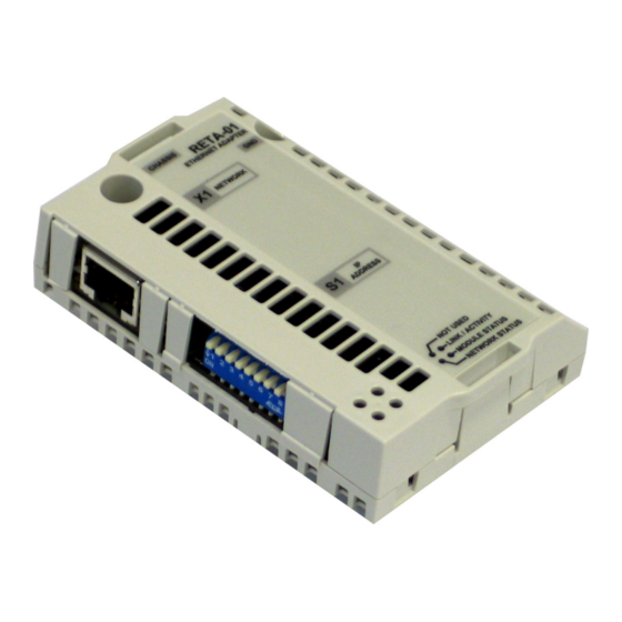
NETWORK STATUS Top view Side view Figure 1. The RETA-01 Adapter module. Compatibility The RETA-01 is compatible with all master stations that support the Modbus/TCP and/or EtherNet/IP protocols. Delivery check The option package for the RETA-01 Ethernet Adapter module contains: •... -
Page 18: Warranty And Liability Information
(12) months after installation or twenty-four (24) months from date of manufacturing, whichever first occurs. The local ABB office or distributor may grant a warranty period different to the above and refer to local terms of liability as defined in the supply contract. -
Page 19: Quick Start-Up Guide
(Printed on a sticker on the back of the module) • Make sure you have the two screws for fastening the module Mechanical installation • Insert the RETA-01 into its specified slot in the drive (SLOT2 for ACS550, SLOT1 for ACS800). • Fasten the two screws. -
Page 20: Network Configuration
• One way of setting the IP address is to use the ARP (Address Resolution Protocol) command from a PC. The new IP address will be stored in the RETA-01 configuration parameters. An example of how to change the IP address from the DOS Prompt window is shown below. -
Page 21: Communication
Communication The module is now ready to operate with Modbus/TCP or EtherNet/IP protocol. The protocol and communication profile used in the application can be selected with a RETA-01 configuration parameter, “PROTOCOL”: Modbus/TCP EtherNet/IP AC/DC communication profile EtherNet/IP ABB Drives communication profile Note: With ACS550 the profile selection is automatic. -
Page 22: Ethernet/Ip Master Configuration
Ethernet/IP master configuration • Add RETA-01 adapter to device configuration Figure 2. RSlogix 5000: Adding new module to I/O Configuration. • Set “comm Format” to “Data-INT”, IP address, input and output assemblies and their sizes. Disable the “Configuration” assembly instance (1) by setting its size to ‘0’. - Page 23 • Use class instance editor to edit the attributes of Ethernet/IP objects if necessary. Figure 3. RSNetWorks for Ethernet-IP: Class Instance Editor Quick start-up guide...
- Page 24 Example 1: Extended Speed Control (AC/DC communication profile) on ACS800 Standard application • Set “comm Format” to “Data-INT” • Set IP address to ‘10.0.0.6’ • Set input assembly instance to ‘71’ and size to ‘2’ • Set output assembly instance to ‘21’ and size to ‘2’ •...
- Page 25 Table 5. Drive configuration for Extended Speed Control Drive parameter Example setting for ACS800 10.01 EXT1 STRT/STP/DIR COMM.CW 10.03 REF DIRECTION REQUEST 11.03 EXT1 REF1 SELECT COMM.REF 16.04 FAULT RESET SEL COMM.CW 98.02 COMM. MODULE LINK FIELDBUS 98.07 COMM PROFILE GENERIC 51.01 MODULE TYPE ETHERNET...
- Page 26 Example 2: User Specific Control (ABB Drives communication profile) on ACS550 • Set “comm Format” to “Data-INT” • Set IP address to ‘10.0.0.6’ • Set input instance to ‘103’ and size to ‘3’ • Set output instance to ‘102’ and size to ‘2’...
- Page 27 51.04 - 51.07 IP ADDRESS 10.0.0.6 51.08 - 51.11 SUBNET MASK 255.255.255.0 51.12 - 51.15 GW ADDRESS 0.0.0.0 51.16 PROTOCOL 2 (ABB Drives profile) 51.19 OUTPUT 1 1 (Command word) 51.20 OUTPUT 2 2 (Reference 1) 51.23 INPUT 1 4 (Status word) 51.24 INPUT 2...
- Page 28 Quick start-up guide...
-
Page 29: Mechanical Installation
Hardware Manual of the drive. Mounting The RETA-01 is to be inserted into its specific position in the drive. The module is held in place with plastic retaining clips and two screws. The screws also provide the earthing of the CAT 5 STP cable shield connected to the module, and interconnect the GND signals of the module and the control board of the drive. - Page 30 Mechanical installation...
-
Page 31: Electrical Installation
Ethernet connection The network cable is connected to the RJ45 connector (X1) on the RETA-01 module. Standard CAT 5 UTP and CAT 5 STP cables can be used. In case CAT 5 STP is used, the cable shield is internally connected to drive frame through the module. - Page 32 Electrical installation...
-
Page 33: Drive Configuration
ABB drives can receive control information from multiple sources including digital inputs, analogue inputs, the drive control panel and a communication module (e.g. RETA-01). ABB drives allow the user to separately determine the source for each type of control information (Start, Stop, Direction, Reference, Fault Reset, etc.). - Page 34 Table 8. The RETA-01 configuration parameters Par. Parameter name Alternative settings Default setting MODULE TYPE (Read-only) ETHERNET Comm rate (0) Auto-negotiate; (1) 100 Mbit/s, (0) Auto-negotiate full duplex; (2) 100 Mbit/s, half duplex; (3) 10 Mbit/s, full duplex; (4) 10 Mbit/s, half duplex DHCP (0) DHCP disabled;...
- Page 35 Output 3 0…65535 Output 4 0…65535 Input 1 0…65535 Input 2 0…65535 Input 3 0…65535 Input 4 0…65535 1 MODULE TYPE This parameter shows the module type as detected by the drive. The value cannot be adjusted by the user. If this parameter is undefined, the communication between the drive and the module has not been established.
- Page 36 4 IP address 1 5 IP address 2 6 IP address 3 7 IP address 4 An IP address is assigned to each TCP/IP node on an Ethernet network. IP addresses consist of four decimal integers in the range of 0…255 separated by periods, each integer representing the value of one byte (8 bits, octet) in the IP address.
- Page 37 When Modbus/TCP protocol is in use, these parameters define the output data words or drive parameters that are updated cyclically between the drive and RETA-01. For the user this can be seen as faster response for the Modbus queries. Drive configuration...
- Page 38 When Modbus/TCP protocol is in use, these parameters define the input data words or drive parameters that are updated cyclically between the drive and RETA-01. For the user this can be seen as faster response for the Modbus queries. When Ethernet/IP protocol is in use, these parameters define the data words or drive parameters that can be read using Assembly object instance 103 (see chapter Communication).
- Page 39 The contents are defined by a decimal number in the range of 0 to 65535 as follows: Not used 1…99 Data set area of the drive Data set 1 word 1 Data set 1 word 2 Data set 1 word 3 Data set 2 word 1 Data set 2 word 2 •...
- Page 40 Drive configuration...
-
Page 41: Network Configuration
Network configuration Overview The network configuration of the RETA-01 can be done using several methods. The following flowchart shows the sequence in which different settings are read. The table below gives detailed information on each different configuration methods. Start switches... - Page 42 Method Description Note DIP switch (S1) By default, the IP address is defined by Only read at software (see chapter Communication). start-up. Setting any DIP actuator to ON enables Only for intranet hardware selection. DIP actuators 1 to 8 use. define the last octet (1 to 254) of the IP address in binary.
- Page 43 DHCP/BOOTP Automatically receive the configuration from A DHCP server a DHCP server. is required on the network. Settings stored Use the configuration stored in the RETA-01 RETA-01 must in RETA-01 configuration parameters. See Table in the be restarted or configuration...
-
Page 44: Data Transfer Rates Supported
Data transfer rates supported The RETA-01 supports 10 Mbit/s and 100 Mbit/s data transfer rates. The RETA-01 automatically detects the data transfer rate used. Other network components RETA-01 uses multicast messages for producing instances. -
Page 45: Communication Profiles
With the RETA-01 module, the Ethernet/IP network may employ either the ODVA AC/DC drive profile or the ABB Drives profile. Modbus/TCP network may employ only the ABB Drives profile. The ODVA AC/DC drive profile This section briefly describes the ODVA AC/DC Drive profiles. -
Page 46: Odva Output Attributes
Instances is recommended. Implicit Messaging allows the Ethernet/IP Master to set or get predefined groups of attributes in a single message exchange. Assembly Instances supported by the RETA-01 are listed and defined in chapter Communication, page 55. ODVA output attributes This section briefly describes the instances found in the ODVA AC/DC Drive Profiles output assemblies. -
Page 47: Odva Input Attributes
Net Ctrl (Control Supervisor Object) This attribute requests that the drive Run/Stop command be supplied locally (Net Ctrl = 0) or by the network (Net Ctrl = 1). Net Ref (AC/DC Drive Object) This attribute requests that the drive speed and torque references be supplied locally (Net Ref = 0) or by the network (Net Ref = 1). - Page 48 Ready (Control Supervisor Object) This attribute indicates that the Control Supervisor Object state machine (see “State” below) is in the Ready, Running or Stopping state. Ctrl From Net (Control Supervisor Object) This attribute indicates if the Run/Stop command is being supplied locally (Ctrl From Net = 0) or by the network (Ctrl From Net = 1).
-
Page 49: Abb Drives Communication Profile
This attribute indicates the actual torque at which the drive is operating. The units are scaled by the Torque Scale attribute of the AC/DC Drive Object. ABB Drives communication profile The control word and the status word The Control Word is the principal means for controlling the drive from a fieldbus system. -
Page 50: References
References References are 16-bit words containing a sign bit and a 15-bit integer. A negative reference (indicating reversed direction of rotation) is formed by calculating the two’s complement from the corresponding positive reference. Actual values Actual values are 16-bit words containing information on the operation of the drive. -
Page 51: Communication
This chapter describes the Modbus/TCP and EtherNet/IP messaging used in the communication with the drive. Protocols The RETA-01 module supports the Modbus/TCP protocol according to Modbus/TCP Specification 1.0, and the EtherNet/IP protocol. User must select, which protocol to use. Communication... -
Page 52: Modbus/Tcp
Modbus/TCP Overview This chapter describes the Modbus/TCP communication protocol for RETA-01. For detailed information on Modbus/TCP communication refer to Modbus/TCP protocol specification 1.0. RETA-01 uses ABB Drives communication profile with Modbus/TCP. Register read and write The drive parameter and data set information is mapped into a 4xxxx register area. - Page 53 Table 12. Parameter mapping Parameter 4GGPP Data sets 40001…40096 00 Data sets 01 Data word 1.1 02 Data word 1.2 03 Data word 1.3 Each data set consists 04 Data word 2.1 of 3 data words. For 05 Data word 2.2 example, ‘Data word 06 Data word 2.3 2.3’...
-
Page 54: Exception Codes
Address does not exist or is read/write-pro- address tected Illegal data Value is outside minimum and maximum value limits. Parameter is read-only Function codes The RETA-01 supports the Modbus function codes shown below. Table 14. Supported function codes Function Name Description Modbus code class... -
Page 55: Ethernet/Ip
(CIP) technology, which is also the framework for both DeviceNet and ControlNet. Ethernet/IP specifies the wiring, and the data transfer through the bus. The RETA-01 module can act as a server on an EtherNet/IP network. Object modelling and functional profiles One of the main features of EtherNet/IP is object modelling. - Page 56 Assembly instances 20, 70, 21 and 71 are used in the AC/DC drive profile and instances 100, 101, 102 and 103 in ABB Drives profile. User selects the profile with RETA-01 configuration parameter 16 PROTOCOL (with ACS800 also parameter 98.07 is changed).
- Page 57 Note: If the Basic Speed Control or the Extended Speed Control assembly is used, it must be ensured that the fieldbus is selected as the drive control source and fieldbus specific (Generic Drive profile) Control/Status Word format is selected instead of ABB Drives profile. Communication...
- Page 58 Extended Speed Control assembly The Extended Speed Control assembly is defined by ODVA AC/DC Drive Profile. The format of the output assembly is: Instance 21 Byte Bit 7 Bit 6 Bit 5 Bit 4 Bit 3 Bit 2 Bit 1 Bit 0 NetRef NetCtrl...
- Page 59 Data definitions Definitions of data in the assemblies are found in the classes specified in the table below. Name CIP class Class Instance Attribute Name Run Forward Control Supervisor Run1 Run Rev Control Supervisor Run2 Fault Reset Control Supervisor FaultRst NetCtrl Control Supervisor NetCtrl...
- Page 60 ABB Drives Control assembly ABB Drive Control assembly allows the use of the ABB Drives profile. The format of the output assembly is: Instance 100 Byte Bit 7 Bit 6 Bit 5 Bit 4 Bit 3 Bit 2 Bit 1...
- Page 61 Output I/O 2 (High Byte) … Output I/O 32 (Low Byte) Output I/O 32 (High Byte) The content of Output I/O 1 to 4 can be configured from RETA-01 configuration parameters. See chapter Drive configuration. Output I/O from 1 to 32 can also be configured through the Vendor Specific Drive I/O Map Object (class 0x91).
- Page 62 Input I/O 2 (High Byte) … Input I/O 32 (Low Byte) Input I/O 32 (High Byte) The content of Input I/O 1 to 4 can be configured from RETA-01 configuration parameters. See chapter Drive configuration. Input I/O from 1 to 32 can also be configured through the Vendor Specific Drive I/O Object (Class 91h).
-
Page 63: Class Objects
Class objects The objects implemented in the RETA-01 module are listed below and described in further detail on the following pages. • Identity Object, Class 0x01 • Message Router, Class 0x02 • Assembly Object, Class 0x04 • Connection Manager, Class 0x06 •... - Page 64 Array the Identity Object [USINT represents USINT] 0x05 Status Status of the Device 0,0,255 WORD 0x06 Serial Serial Number of the N/A,N/A, UDINT Number EtherNet module 0x07 Product Product identifica- RETA-01 and Short String Name tion (32 characters max.) Communication...
- Page 65 E.g. 2 = AC drive, 13 = DC drive Product Code Every ABB drive type or application of the drive has a dedicated product code. Revision Revision attribute, which consists of Major and Minor Revisions, identifies the Revision of the RETA-01 application.
- Page 66 4,5,6,7 Extended device status information 0000 = Unknown 0010 = Faulted I/O connection 0011 = No I/O connection established 0100 = Non-volatile configuration bad 0110 = Connection in Run mode 0111 = Connection in Idle mode Minor Recov- TRUE indicates the device detected a recoverable erable Fault problem.
-
Page 67: Message Router, Class 0X02
Message Router, Class 0x02 Services Class services: – Instance services: – Assembly Objects, Class 0x04 The Assembly Objects binds attributes of multiple object together. This allows data of the objects to be sent and received over a single connection. Assembly objects can be used to bind input data or output data. -
Page 68: Connection Manager, Class 0X06
Run/Idle bit. Run/Idle operation for AC/DC Drive profile can be defined in Control Supervisor Object’s (Class 0x29) attribute NetIdleMode (20) and for ABB Drives profile in Configuration Object (Class 0x92) attribute IdleAction (7). (RETA-01 version 2.05 onwards) Class 3 Connections Class 3 connections are used to establish connections to the message router. -
Page 69: Control Supervisor Object, Class 0X29
Instance 0x01, Attributes Attribute Services Description Motor Dflt, Data type name type Min, 0x03 Motor type AC/DC 7,7,7 UINT 0x06 Rated Cur- Get/Set Rated Stator Cur- AC/DC UINT rent rent from motor nameplate. 0x07 Rated Volt- Get/Set Rated Base Volt- AC/DC UINT age from motor... - Page 70 Instance 0x01 attributes Attribute Services Description Data type name 0x03 Run 1 Get/Set 0 = Stop, 1 = Run BOOL 0x04 Run 1 Get/Set 0 = Stop, 1 = Run BOOL 0x05 Net Control Get/Set 0 = Local Control, BOOL 1 = Network Control 0x06 State 1 = Start/up...
-
Page 71: Ac/Dc-Drive Object, Class 0X2A
Supported only with assembly instance 21 Supported only with assembly instances 70 and 71 Supported only with assembly instance 71 Supported only from RETA-01 version 2.05 onwards AC/DC-Drive Object, Class 0x2A This object models the functions specific to an AC or DC Drive and is accessible only when using AC/DC Drive profile. - Page 72 Instance 0x01, Attributes Attribute name Services Description Data type 0x03 At Reference Frequency arrival BOOL 0x04 NetRef Get/Set Requests torque or speed reference BOOL to be local or from the network. 0 = Set Reference not net Control 1 = Set Reference at net Control Note that the actual status of torque or speed reference is reflected in attribute RefFromNet 0x1D (29).
-
Page 73: Vendor Specific Object, Class 0X90
Vendor Specific Object, Class 0x90 The Vendor Specific Object, Class 0x90, enables access of drive parameter and data sets. Services Class services: Get Attribute Single Instance services: Get Attribute Single Set Attribute Single To access drive parameters, Instance and Attribute must correspond to the drive parameter Group and Index as follows: •... - Page 74 Instance 0x63 (Group 99), Attributes Attribute name Services Description 0x01 Parameter Index Get/Set Group 99 Index 1 0x02 Parameter Index Get/Set Group 99 Index 2 … 0x63 Parameter Index Get/Set Group 99 Index To access data sets, Instance is always 100. Attribute corresponds to a specific data word.
-
Page 75: Drive Io Map Object, Class 0X91
This is a vendor specific object that is used for mapping data to the User Specific Control assembly instances 102 and 103. Input and Output parameters 1 to 4 correspond to the input and output parameters represented in Table 8. The RETA-01 configuration parameters. See chapter Drive configuration. Maximum of 32 words of Input and Output can be defined in total. -
Page 76: Configuration Object, Class 0X92
RETA-01 configuration parameters 19-26. Configuration Object, Class 0x92 This object is used to set the Idle action in ABB Drives profile. Most Ethernet/IP masters implement the Run/Idle header and this class was created to be able to define the drive behaviour in Idle mode. -
Page 77: Tcp/Ip Interface Object, Class 0Xf5
Instance Attributes Name Services Description Dflt,Min,Max Data type 0x07 Idle Action Get / Set 0, 0, 1 UINT 0 = Imitate commu- nication fault func- tion 1 = Ignore idle TCP/IP Interface Object, Class 0xF5 This object provides a mechanism of configuring the TCP/IP settings via EtherNet/IP. - Page 78 N/A, N/A Capable of obtaining network configuration via DHCP. 0x03 Configuration Get/Set 0 = Configuration from N/A, 0, 2 DWORD Control RETA-01 configuration parameters; 2 = Configuration from DHCP 0x04 Physical Link Physical link -> Ethernet Array[] Object object Path size...
-
Page 79: Ethernet Link Object, Class 0Xf6
Ethernet Link Object, Class 0xF6 This object maintains link-specific counters and status information for the Ethernet communication interface. Services Class services: Get Attribute All Get Attribute Single Instance services: Get Attribute All Get Attribute Single Class Attributes Attribute Services Description Dflt,Min,Max Data type name 0x01 Revision... - Page 80 Communication...
-
Page 81: Fault Tracing
Fault tracing LED indications The RETA-01 module is equipped with three diagnostic LEDs. The description of the LEDs is below. (not used) Link/Activity Network Status Module Status Name Colour Function Flashing green - Module is receiving/transmitting on Ethernet Green Steady green - Module has detected link... - Page 82 Fault tracing...
-
Page 83: Technical Data
Technical data RETA-01 Enclosure: 34 mm CHASSIS RETA-01 PROFIBUS ADAPTER NETWORK ADDRESS NOT USED LINK / ACTIVITY MODULE STATUS NETWORK STATUS 62 mm Mounting: Into the option slot on the control board of the drive. Degree of protection: IP20 Ambient conditions: The applicable ambient conditions specified for the drive in its Hardware Manual are in effect. -
Page 84: Ethernet Link
Current consumption: • 380 mA average (5 V), supplied by the control board of the drive General: • Estimated min. lifetime: 100 000 h • All materials UL/CSA-approved • Complies with EMC standards EN 50081-2 and EN 50082-2 Ethernet link Compatible devices: Ethernet standard IEEE 802.3 and 802.3u devices Medium: 10base-TX or 100base-TX... - Page 86 ABB Oy ABB Inc. ABB Beijing Drive Systems AC Drives Automation Technologies Co. Ltd. P.O. Box 184 Drives & Motors No. 1, Block D, FIN-00381 HELSINKI 16250 West Glendale Drive A-10 Jiuxianqiao Beilu FINLAND New Berlin, WI 53151 Chaoyang District Telephone +358 10 22 11 Beijing, P.R.
Need help?
Do you have a question about the RETA-01 and is the answer not in the manual?
Questions and answers