Table of Contents
Advertisement
Quick Links
- 1 Smoke Detection Function Deactivation
- 2 Installing the Detector as a Standalone Device
- 3 Installing the Detector in Association with a Daitem Alarm System
- 4 Installing the Detector as Part of a Network
- 5 Testing the Detector
- 6 Using the Detector
- 7 Fault Indications
- 8 Maintenance
- Download this manual
Advertisement
Table of Contents

Related Manuals for DAITEM SH151AX 3


Summary of Contents for DAITEM SH151AX 3
- Page 1 Smoke and heat detector with radio system, 10 year-battery SH151AX 3 Installation Manual...
-
Page 2: Table Of Contents
....104 5.3 In case of work in the home.... 117 2.5 Installing the detector in association with a Daitem alarm system.... 106 6. Technical data ........117 2.6 Installing the detector as part Guarantee certificate....... 119 of a network........ - Page 3 0:40 2:25 The smoke detection function can be disabled (see chapter 2.2) It can be: • used alone, • included in a Daitem alarm system with TwinBand control panel, ® • interconnected in a wireless network with 40 detectors maximum.
-
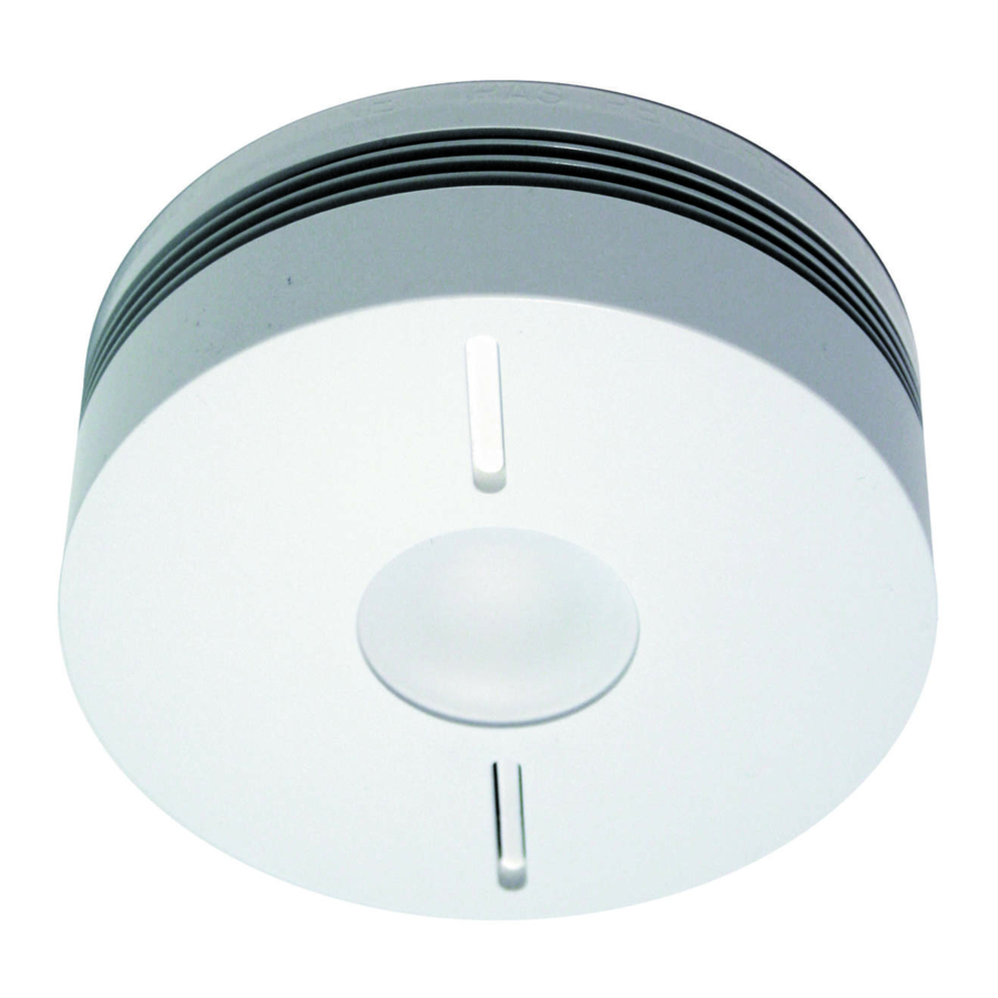
Page 4: Description
15 minutes. When connected to a Daitem alarm system, the detector also generates: • triggering of the control panel and wireless sirens in fire sounding mode for 5 min, •... -
Page 5: Installation
2. Installation 2.1 Guarantee sticker Remove the guarantee sticker from inside the packaging and stick it to the guarantee certificate provided in this manual or use the guarantee certificate supplied with the main product. 2.2 Smoke detection function deactivation The smoke detection function can be deactivated while the heat detection function remains enabled (e.g. -
Page 6: Choosing The Best Place To Install The Detector
2.3 Choosing the best place to install the detector The detector must be placed: • in rooms where there is a fire hazard (living rooms with fireplace, children’s bedrooms, occupied lofts or basements, etc.). The detector can also be installed in areas with a harsh or difficult environment such as kitchens (cooking fumes), garages (smoky atmosphere), and other uninhabited areas that are often dusty as long as the smoke detection function is deactivated (see chapter 2.2) (Fig. - Page 7 Minimum protection: a detector in a corridor or stairwell at every level A detector and in every bedroom can be added Optimum protection: to the kitchen minimum detection if the smoke extended with the detection addition of a detector in function is each living area or deactivated...
-
Page 8: Installing The Detector As A Standalone Device
2.4 Installing the detector as a standalone device Use the LED alignment arrow on the base in order to position the detector in the best possible manner (see Description). 1. Fix the base keeping in mind the 2. Position the detector on its base making precautions outlined in the chapter entitled sure the arrow on the base and the LEDs Choosing the best place to install the... - Page 9 3. Turn the locking ring clockwise so that the identification mark is aligned with the LEDs. The yellow indication LED flashes for 5 s and then once every 10 s to indicate the detector is operating normally. Locking ring Align mark and LEDs 4.
-
Page 10: Installing The Detector In Association With A Daitem Alarm System
2.5 Installing the detector in association with a Daitem alarm system Recognition programming allows the detector to be recognised by the control panel. The control panel allocates a detector number following the chronological order of programming. All the radio detector must be recognized and in radio range with the control panel. - Page 11 1. Perform the following programming sequence: then “beep, fire detector n° X” 10 s max. Press then # on the Press and hold the Cfg2 key for 10 s until the control control panel keypad panel responds 2. Keeping in mind the precautions outlined in the chapter entitled Choosing the best place to install the detector, position the detector in the chosen location without fixing it in place.
-
Page 12: Installing The Detector As Part Of A Network
2.6 Installing the Alarm detector as part control of a network panel It is possible to interconnect up to 40 detectors so that all the detectors in the home as well as the alarm system can be Detectors triggered together. The responses to detection are described in chapter 1.1 How the detector works. - Page 13 2. Press the test button on one of the detectors until the red LED on all the other detectors lights up steadily. 3. Lightly press on the Cfg1 key on all of the detectors to exit recognition programming mode. Without press on the Cfg1 key the detectors outside the programming mode after one minute.
- Page 14 4. Test the radio range. A. Put all the detectors in test mode by pressing once on the Cfg1 button. The red LED lights up for 5 sec and then flashes. B. Press the test button on one of the detectors and the detector will test the radio range in permanent transmission mode.
- Page 15 2.7 Installing the detector as a relay If the radio range between all the detectors is insufficient, one of the detectors can be programmed as a relay. This means that it will re-transmit alarms received to all the other detectors. IMPORTANT: a detector programmed as a relay only relays an alarm to the other detectors.
-
Page 16: Testing The Detector
To programme a detector as a relay: 1. Press Cfg1. After 4 s, the red LED flashes. Keep holding the button down. 2. After 10 s, the flashing speeds up or slows down: - if the flashing speeds up, the relay function has been activated, - if the flashing slows down, the relay function is still deactivated. -
Page 17: Using The Detector
Please note that the alarm can be stopped 20 s after the detector triggers the system. If the detector is associated with a Daitem alarm system (see chapter 2.5), press the “Off” key on a remote control device to stop the control panel and sirens. - Page 18 If the detector is Installed as a standalone device: • press the test button, • press 2 times one of the keys on the remote control pointed on the detector. If the detector is part of a network: The detector(s) having been activated (red LED flashing) must be stopped to end network sounding.
-
Page 19: Fault Indications
4.3 Fault indications In order not to wake you up, alarms resulting from mains supply problems or dirty sensors are shut down during the night. Any errors are corrected after daybreak within 10 minutes i.e. 8 hours after the event. 4.3.1 Power fault Detector at the source Other interconnected detectors... -
Page 20: Maintenance
IMPORTANT • If sounding continues after a postponement attempt, this means that the detection head is not working. Replace the detector. • If the detection head fault indication occurs at night, this means that it is not working. Replace the detector. •... -
Page 21: In Case Of Work In The Home
5.3 In case of work in the home The detector must not be painted. If work is to be carried out after the detector has been installed, cover it completely. IMPORTANT: do not forget to remove the protection when the work is finished. 6. - Page 22 Manufacturer: Hager Security SAS Address: F-38926 Crolles Cedex - France Product type: Smoke and heat detector Trade mark: Daitem We declare under our sole responsibility that the product to which this declaration relates is compliant with the essential requirements of the following directives: •...
-
Page 23: Guarantee Certificate
• When installing a complete system, use the guarantee certificate supplied with the main product. GM Techtronics Ltd. - Unit 17 Paxcroft Farm Hilperton - Trowbridge - Wiltshire - BA14 6JB England Installer’s stamp (mandatory) Box for Daitem use only Received on:... - Page 24 User’s contact details: Surname/name of company: ......................... First name:..............................Address:................................. Town: ................................Post code..........Tel....................■ Installation ■ After-sales replacement Date of purchase: _________ / _________ / _________ Product serial n°...
- Page 25 To obtain advice when installing your system or before returning equipment, please contact the Daitem technical support team (see telephone number at the back of the alarm system installation manual) or check the web site at www.daitem.co.uk A team of qualified technicians will advise you what to do.
Need help?
Do you have a question about the SH151AX 3 and is the answer not in the manual?
Questions and answers