Table of Contents
Advertisement
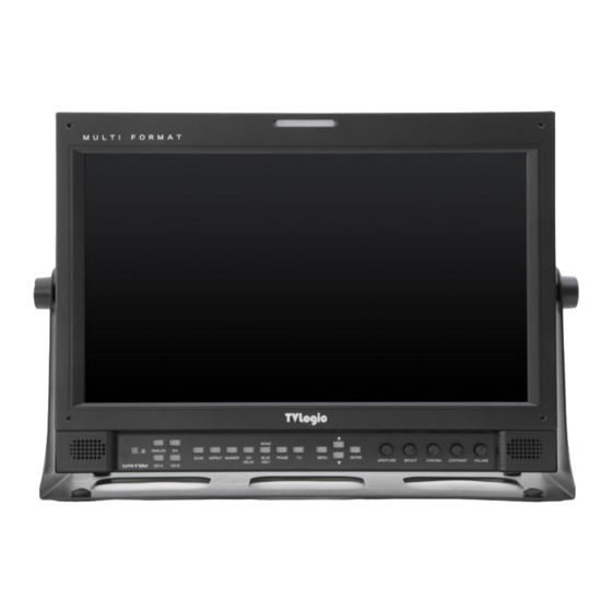
MULTI FORMAT
BROADCAST MONITOR
SERVICE MANUAL
MODEL NAME:
LVM-173W-3G 17" MULTI FORMAT BROADCAST MONITOR
KEEP THIS SERVICE MANUAL FOR FUTURE REFERENCE.
PLEASE CALL 82-70-8668-6611 OR EMAIL TO
support@tvlogic.co.kr
FOR ASSISTANCES
IF YOU HAVE ANY QUESTION ABOUT LVM-173W-3G MODEL.
THIS INFORAMATION OF THIS MANUAL IS SUBJECT TO CHANGE WITHOUT ANY NOTICE.
Advertisement
Table of Contents

Related Manuals for TVLogic LVM-173W-3G


Summary of Contents for TVLogic LVM-173W-3G
- Page 1 LVM-173W-3G 17” MULTI FORMAT BROADCAST MONITOR KEEP THIS SERVICE MANUAL FOR FUTURE REFERENCE. PLEASE CALL 82-70-8668-6611 OR EMAIL TO support@tvlogic.co.kr FOR ASSISTANCES IF YOU HAVE ANY QUESTION ABOUT LVM-173W-3G MODEL. THIS INFORAMATION OF THIS MANUAL IS SUBJECT TO CHANGE WITHOUT ANY NOTICE.
- Page 2 The troubleshooting section of this manual is intended to provide a quick reference concerning issues that occur most frequently through customer complaints. We hope that technicians will repair LVM-173W-3G without any problem through our service manual. SERVICE PREPARATION: A clean work area at the start of each job is essential for efficient service work.
- Page 3 SAFETY PRECAUTIONS ABOUT ASSEMBLY - Drawing can’t be revised without TVLogic’s permission. - Drawing can’t be revised without TVLogic’s permission. - Please set torque at 2K of electronic screw driver when...
- Page 4 2.CONTROLS & FUNCTIONS...
- Page 5 3.FRONT KEY BUTTON...
- Page 6 4.MONITOR DRAWING...
- Page 7 5.EXPLODED DIAGRAM...
- Page 8 6.1 DISASSEMBLY PROCEDURE 1) Loosen and remove 2 stand knobs on 2) Release the screws. Then separate the both sides of LVM-173W-3G. stand from the product. 4) Disconnect all the cables around 3) Loosen and remove all the screws the main board cover.
- Page 9 6.2 DISASSEMBLY PROCEDURE 5) Release all the screws on the main board 6) Remove all the screws on the main Cover DVI and HDMI. board cover. 8) Loosen and remove all the screws 7) Take the main board cover away from attached to the main board and the product.
- Page 10 6.3 DISASSEMBLY PROCEDURE 9) Remove all the screws attached to the 10) Remove all the screws attached to the KP-305 and pull up the KP-305. KP-306 and pull up the KP-306. 11) Disconnect the LVDS Cable. 12) Release screws on the socket bracket and dismount it.
- Page 11 6.4 DISASSEMBLY PROCEDURE 13) Loosen and remove all the screws on 14) Loosen and remove screws on the speaker the Front and dismount the key Pad and dismount the speaker. board. 15) Separate the Front from the main 16) Remove all the screws on the side bracket.
- Page 12 6.5 DIASSEMBLY PROCEDURE 17) Separate the tally board from the 18) Separate the tally from the front. front. 20) Rear 19) Front...
- Page 13 Other Functions 7. DVI ANALOG/ DVI DIGITAL / HDMI RESOLUTION DVI ANALOG/DVI DIGITAL/HDMI Support Resolution(LVM-173W-3G) • DVI-ANALOG mode supports the following modes : Resolution Frequency 640 × 480 60Hz, 75Hz 720 x 400 70Hz 800 × 600 60Hz, 72Hz, 75Hz 1024 ×...
- Page 14 8.PRODUCT SPECIFICATIONS LVM-173W-3G 1 x DVI-I DVI-I(RGB) IN 3 x BNC Analog Input Input 2 x BNC SDI A/B Channel Input 1 x HDMI HDMI Input 3 x BNC Analog Output Output 2 x BNC SDI A/B Channel (Loop Through Out)
- Page 15 9. PCB BLOCK DIAGRAM...
- Page 16 SAFETY AREA 80%, SAFETY AREA 85%, SAFETY AREA 88%, SAFETY AREA 90%, SAFETY AREA 93%, SAFETY AREA 100%, 708, 608(LINE 21), 608(ANC), DYNAMIC-UMD <LVM-173W-3G> - PIN 7 is POWER ON/OFF use only, PIN 8 is GND. < Video Input >...
- Page 17 11. PROGRAM UPDATE – WEBHARD TVLOGIC WEBHARD INFORMATION If you need to upgrade to a new firmware with TVLogic monitors, please visit the TVLogic webhard at h p://tvlogic.webhard.co.kr/english ID: dealer Password: XXXXXXXXX Please request the password from TVLogic overseas sales team.
- Page 18 12.1 PROGRAM UPDATE WITH ETHERNET 1) Monitor Settings - In the OSD Menu -> REMOTE -> Enter IP Address, Subnet Mask, Gateway value. * Changing the PORT NO. is not recommended. * Enter the IP Address of the connected internet with monitor. * PASSWORD feature is available with Ver.
- Page 19 12.2 PROGRAM UPDATE WITH ETHERNET 3) Firmware update - FPGA Picture 2 : Update setting * Select FPGA #1 for DEV in UPDATE PROCESS. Then, OPEN and select the FPGA firmware file. * Press the SEND button to start transferring the firmware file to the Ethernet Board.
- Page 20 12.3 PROGRAM UPDATE WITH ETHERNET Picture 4: Update start message window => * Press the “OK” button to start updating. CONFIG SUCCESS message window => Picture 5: * “CONFIG SUCCESS” message window appears when update is finished. * Select ARM/GEN for DEV in UPDATE PROCESS. Then, OPEN and select the ARM/GEN firmware file.
- Page 21 12.4 PROGRAM UPDATE WITH ETHERNET BOARD 4) How to Upgrade ETHERNET BOARD Picture 6: ETHERNET BOARD Upgrade SW - Connect the serial port of the PC and the RS232 port of monitor with a cable. The PC must have RS232 port and cannot use the USB for RS232 converter. See Picture 7 for the cable connection.
- Page 22 12.5 PROGRAM UPDATE WITH ETHERNET BOARD 2 : RX 2 : RX 3 : TX 3 : TX 4 : DTR 4 : DTR MONITOR RS232 5 : GND 5 : GND RS232 MALE MALE 6 : DSR 6 : DSR 7 : RTS 7 : RTS 8 : CTS...
- Page 23 13.1 PROGRAM UPDATE WITH USB 1) Install the CyUSB driver on your PC. 2) Turn on the monitor after connecting the PC with monitor by USB Cable. 3) Upgrade program settings - Run LCD_PROG.exe - Check the connection in PROGRAMMER STAUS.
- Page 24 13.2 PROGRAM UPDATE WITH USB CAUTION: FPGA A, CPU and VXP should be separately updated. 4) Firmware update -FPGA Picture 1: FPGA setting * Select FPGA type form check box in PROGRAM STATUS. * Select the FPGA type check box in PROGRAM STATUS. * Select Bank0 from bank selection window.
- Page 25 13.3 PROGRAM UPDATE WITH USB Picture 2: Download complete message window * Update will be proceeded after Download complete. Update status appears in SIZE/MSG -CPU/GEN -CPU/GEN * Select CPU/GEN type from check box in PROGRAM STATUS. * Select the CPU/GEN check box in PROGRAM STATUS. * Select Bank0 from bank selection window.
- Page 26 Please read the following calibration instruction before starting calibration software with Monitors. ▪ Avoid shocks or vibrations when calibrating TVLogic monitors. These may damage the unit and cause it to malfunction. ▪ Wait minimum 20 minutes before starting calibration with TV Logic monitor.
- Page 27 Any compatible 24 bit video card Designed for windows 98/2000/XP that supports the 1024 x 768 resolution Step 1 TVLogic Calibration Program Installation 1.1 Launch “CalibratorSetup.exe” 1.2 The “Calibration program setup window” will launch as shown below Please click the “Next” button.
- Page 28 14.3 CABLIBRATION S/W INSTALLATION 1.3 Designate the location where the program will be installed in your PC, and click the “Next” button. 1.4 If the user sees the image below, the installation was successful. 1.5 Please copy “LicenseKey.tvl” file into the \bin folder (found under the Calibration program directory)
- Page 29 14.4 CABLIBRATION S/W INSTALLATION 2. CALIBRATION The purpose of our calibration tool is to optimize the colors of LCD displays by compensating factors which affect the LCD panel. This calibration program is used for all of our LCD monitors. For a detailed calibration procedure, please refer to the following.
- Page 30 14.5 CABLIBRATION S/W INSTALLATION If you are connecting an X-Rite, CA-210, CS-200, or an Eye-One, connect the probe with the PC through the USB port. Those probes which connect with USB should install the device driver offered by the measurement device company. (The XVM-245W supports the Klein K-10, Konica-Minolta CA-210, CS-200 and X-Rite i1 Display3 probes) Put the measurement device facing toward the center of the monitor.
- Page 31 14.6 CABLIBRATION S/W INSTALLATION CALIBRATION PROCEDURE 1. Launch the calibration program. The main window appears as below. Fig 2 Calibration main window 2. The probe and the monitor’s ports will be displayed on the top of the screen. If see the port’s sign highlighted in green, it the monitor and the probe is well connected.
- Page 32 14.7 CABLIBRATION S/W INSTALLATION 3. Our calibration software supports the automatic detection of the applied model 3. Our calibration software supports the automatic detecting of the applied model connected for most of our monitors. connected for most of our monitors. However, monitors using the Genesis scaler (LVM-071W, LVM-091W, LVM-XX2W, FCM However, monitors using the Genesis scaler (LVM- 071W, LVM- 091W, LVM- XX2W, FCM and LHM series) does not support feature.
- Page 33 14.8 CABLIBRATION S/W INSTALLATION 7. A message stating “Finished calibrating LCD Panel” will be displayed if your calibration procedure was successful. Fig 5 Completed calibration...
- Page 34 1. To save the calibration result data, please click the “Save” button. Fig 6 Save calibration result 2. Input the Monitor’s serial number (or File name) Fig 7 Save file dialog 3. File will be saved under the directory: “C:/Program Files/TvLogic/Calibrator/data”...
- Page 35 14.10 CABLIBRATION S/W INSTALLATION 3. CL-SOFT SETTINGS The Settings menu is located on the bottom left hand side of the calibration program. Under the Settings menu, you can set the following various settings. Calibration Tab Fig 8 Setting calibration dialog Gamma Gamma 2.2 is the default setting.
- Page 36 14.11 CABLIBRATION S/W INSTALLATION Measurement Steps When adjusting the Gamma value, each measuring interval from 1 to 64 steps can be selected. The lower the figure, the more precise measuring data can be achieved. The recommended step size is 16. Measuring Device The user can choose from 6 different probes: Klein K-10, X- Rite (DTP94), CA-210, CS-200, DK-PM5639 and the Eye-One.
- Page 37 14.12 CABLIBRATION S/W INSTALLATION Comm Tab Fig 9 Setting communication dialog Measuring Dev Measurement device port selection Device: Klein K-10 , X-Rite (DTP94), CA-210, CS-200, DK-PM5639 EYE-ONE, Specbos 1211 Measuring Device Selection: The user can choose from 7 different probes: Klein K-10, X-Rite (DTP94), CA-210, CS-200, DK-PM5639 , Specbos 1211, i1Display2 and the i1Display3.
- Page 38 14.13 CABLIBRATION S/W INSTALLATION Monitor Fig 10 Setting pattern dialog Input Pattern/Output Pattern The user can display the input pattern or output pattern on the monitor. The input level can be selected between the ranges of 50, 85 and 100. Each output level for R, G, and B can be selected from 0 to 255 (8 BIT) and 1024 step (10 BIT).
- Page 39 14.14 CABLIBRATION S/W INSTALLATION Backlight Fig 11 Setting backlight dialog Backlight Stabilization After powering up, the LCD panel needs some time for the stabilization of the backlight. This process takes about 20 ~ 60 min. We recommend the user to choose the “Backlight Stabilization”.
- Page 40 14.15 CABLIBRATION S/W INSTALLATION COLOR TAB LEM/ XVM MODEL Fig 12 Setting XVM&LEM model dialog Color Space Color space selection for XVM and LEM Calibration 3D LUT Write: Save the loaded LUT to connected monitor. LUT Manager: User’s LUT support function User Gamut If the “User”...
- Page 41 14.16 CABLIBRATION S/W INSTALLATION Import Tab Fig 13 Setting LUT 1D LUT This channel is used to apply the stored 1D LUT File to the monitor. 3D LUT This channel is used to apply the stored 3D LUT File to the monitor. CSC File This channel is used to apply the stored CSC File to the monitor.
- Page 42 14.17 CABLIBRATION S/W INSTALLATION K-10, i1 Display3 Setting Dialog Fig 14 Device Setting When the K-10 or i1 Display3 is connected to PC for the first time, the “Device Setting” pop- up appears as shown above. (Fig 14) Default LCD This channel is used for color calibration of normal LCD display which is CCFL backlight type.
- Page 43 14.18 CABLIBRATION S/W INSTALLATION Uniformity Calibration (XVM-245W) To proceed the Panel Uniformity Calibration of XVM-245W, please refer to the following: Fig 15 Calibration Uniformity Center: 980, Auto Move: Unchecked After clicking the button, the Calibration Uniformity pop-up appears as below. Then set the values as follows: Center: 980, Auto Move: Unchecked Fig 16 Calibration Uniformity Dialog...
- Page 44 14.19 CABLIBRATION S/W INSTALLATION Click “Calibrate” bu on to start the Uniformity Calibra Click “Calibrate” button to start the Uniformity Calibration. A er st ng the procedure, a black mark will be appeared on the center of the screen. Put the measurement device on the black mark and click the next step bu on.
- Page 45 15. CIRCUIT BOARD LAYOUT LVDS-J26 LVDS - J30 ENCODER-J24 IC35 IC26 IC42 IC59 IC58 IC45 IC44 IC50 IC23 ETHERNET -J46 SMPS-J8 INVERTER-J34...
- Page 46 16.1 OSCILLOSCOPE • SDI_IN • SDIA_THRU • AUDIO_DIN...
- Page 47 16.2 OSCILLOSCOPE • EM_AUDIO_L • RIGHT_O+ • DATA_IN_A...
- Page 48 16.3 OSCILLOSCOPE • PCLK_OUT • FGN0 • LCD_CLK...
- Page 49 16.4 OSCILLOSCOPE • LCD_HS • TXOCP • VXP_OUT...
- Page 50 17.1 PIN ASSIGNMENT SPECIFICATION Symbol Symbol ENET_TX + CB_RX ENET_YX - CB_TX ENET_RX + CB_DSR ENET_RX - CB_CTS Reference No : J20 Item : RS232 Control Symbol USB_IF - USB_IF + Reference No : J46 Item : Ethernet Reference No : J49 Item : USB...
- Page 51 17.2 PIN ASSIGNMENT SPECIFICATION Symbol Symbol BKL_SCL REMOTE6 BKL_SDA POWER_EN BKL_CTRL BKL_EN 5V_STB Reference No : J32 Item : Key Control Symbol 24Vdc Reference No : J8 Item : SMPS to Board 24Vdc Reference No : J18 Item : DC Jack...
- Page 52 17.3 PIN ASSIGNMENT SPECIFICATION Symbol Symbol RIGHT_0 + RIGHT_0 - LEFT_0 + LEFT_0 - Reference No : J31 Item : Speaker Symbol BKL_SCL APERTURE_A BKL_EN APERTURE_B BKL_CTRL BRIGHT_A BKL_SDA BRIGHT_B Reference No : J34 CHROMA_A Item : Inverter CHROMA_B VOLUME_A VOLUME_B CONTRAST_A CONTRAST_B...
- Page 53 17.4 PIN ASSIGNMENT SPECIFICATION Symbol Symbol MOD_PWR MOD_PWR TALLY_R / Y MOD_PWR MOD_PWR TALLY_G / Y 3.3V Reference No : J36 Item : Tally TXO3P TXO3M TXOCP Symbol TXOCM TXO2P TXO2M TXE4M TXO1P TXE4P TXO1M TXO0P TXO0M TXO4M TXE3P TXO4P TXE3M TXECP TXECM...
- Page 54 17.5 PIN ASSIGNMENT SPECIFICATION Symbol Symbol TX_H AUGND TX_L RX_H EXT_RIN EXT_LIN Reference No : J15 RX_L Item : Audio In Symbol AUGND RIGHT MUTE Reference No : J21 Item : GPI In LEFT Reference No : J16 Item : Audio Out...
- Page 55 17.6 PIN ASSIGNMENT SPECIFICATION Symbol Symbol REMOTE0 TX_H REMOTE1 TX_L REMOTE2 RX_H REMOTE3 REMOTE4 REMOTE5 RX_L REMOTE6 Reference No : J23 Reference No : J22 Item : GPI Remote Item : GPI Out...
- Page 56 18. PACKAGE DRAWING...
- Page 57 MEMO Developed by For more information please visit : http://www.tvlogic.tv #914 Acehighend Tower 8, 345-4 Gasan-dong, Geumcheon-gu, Seoul, 153-782, KOREA Tel : +82-70-8668–6611, Fax : +82-2-6123–3201, Email: sales@tvlogic.co.kr...
Need help?
Do you have a question about the LVM-173W-3G and is the answer not in the manual?
Questions and answers