Advertisement
Quick Links
Advertisement

Subscribe to Our Youtube Channel
Summary of Contents for Aztech AZ-120
- Page 1 INSTALLATION GUIDE AZ-TECH EXTERNAL SOUNDERS...
- Page 2 CONTENTS Page 1 Contents Page 2 External Sound Unit Introduction & Description of Selectable features Page 3 Mounting the External Sound Unit Installing the External Sound Unit / Sounder Connections Page 4 Set-up and Operation procedure Page 5 Indications of Alarm status - Flashing LED indicators Installing Multiple Units - Connecting two or more units Page 6 Safety, Servicing &...
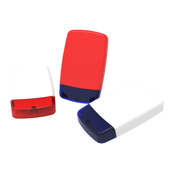
- Page 3 INSTALLATION GUIDE EXTERNAL SOUND UNIT - INTRODUCTION Your AZ-TECH External Sounder with on-board Strobe unit is designed to form an integral part of any Residential or Commercial Security Alarm System. The Unit has certain selectable features with which we recommend that you familiarise yourself prior to commencing installation. Battery ON / OFF: Your Sounder has its own on-board NiMH back-up battery.
- Page 4 We recommend you wire into the Sound Unit first and the Control Panel second. AZ-120 ( Fig.1) If you are wiring in a basic model AZ-120 unit ( ie. without SAB function or anti-tamper) then you do not need to connect to the TAMPER RETURN.
- Page 5 SET-UP AND OPERATION Recommended initial Set-up procedure and selectable features: Select SAB or SCB mode as required using the appropriate jumper. Check that the ‘Timer’ jumper is set to 5 second Test. Place the Battery jumper in the ON position. The sounder will now operate for 5 seconds, and then stop.
- Page 6 INDICATIONS OF ALARM STATUS The on-board Twin LED’s indicate the current status of the Sound Unit and the nature of any Alarm trigger that has occured. Alternate flashing LED’s - Indicate that the Unit is in stand-by mode ready to operate. Simultaneous flashing LED’s giving two pulses indicates an Alarm trigger resulting from a Tamper or Alarm activation.
- Page 7 SAFETY Installation and maintenance should only be carried out by qualified personnel. All strobes generate high voltages which can remain for some time after the supply has been removed. NEVER activate the strobe whilst the PCB is outside of its protective case. For maintenance purposes, should you need to access the circuit by removing the PCB protective cover, avoid touching that part of the circuit labelled ‘WARNING HIGH VOLTAGE’...
- Page 8 WIRING CONNECTION GUIDE - FOR MOST POPULAR ALARM CONTROL PANELS Connections For ‘ADE’ (Honeywell) Panels Connections For CASTLE CARE-TECH Panels Accenta G3 / G4, Optima, Compact, Logic 4 etc. AZTECH ESU STROBE + AZTECH ESU NOT CONNECTED SABT TAMP RTN...
- Page 9 Connections For C&K Intellisense, Challenger Control Panels Bravo 700 ST802 ST700L/ST800L AZTECH ESU TAMP RTN BELL TR - SUPPLY + Bell + Bell + Bell + ( or V+) SUPPLY - Aux - Bell - (or V -) STROBE -...
-
Page 10: Technical Specification
TECHNICAL SPECIFICATION SPECIFICATION AZTECH AZTECH AZTECH AZ-120 AZ-220 AZ-320TW 112dB 115dB 118dB Sound Output @ 1 M Sounder Type Single Piezo Single Piezo Twin Piezo 90 flashes / min 90 flashes / min 90 flashes / min Strobe - Xenon tube... - Page 11 INSTALLER REGISTRATION FORM Please complete and return this form to Kinetic Electronics Limited. We can then send you any updated product information, current promotions etc. Name: Position: Company: Tel: Address: Fax: E-Mail: Post Code: Which distributors do you regularly buy from? How many Alarm Systems do you install each month? How many of the following ‘Kinetic’...
- Page 12 Kinetic Electronics Limited Unit 7 Stakehill Industrial Estate Middleton Manchester M24 2RW Tel: 0161 654 9595 Fax: 0161 654 9596 Email: sales@kinetic-security.co.uk www.kinetic-security.co.uk RoHS...
Need help?
Do you have a question about the AZ-120 and is the answer not in the manual?
Questions and answers