Table of Contents
Advertisement
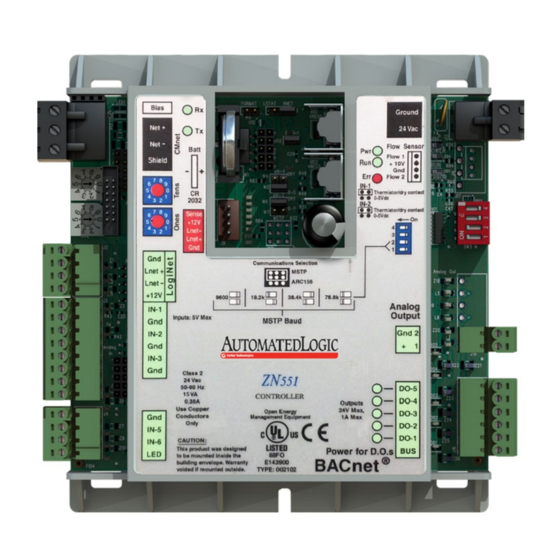
ZN551 Control Module
Technical Instructions
Automated Logic Corporation • 1150 Roberts Blvd. • Kennesaw, GA 30144 • 770/429-3000 • Fax 770/429-3001 •
www.automatedlogic.com • © 2005 Automated Logic Corporation. All rights reserved throughout the world. Automated
Logic Corporation, the Automated Logic logo, WebCTRL, EIKON, BACview, SuperVision, and InterOp are registered
trademarks, and Alert is a trademark of Automated Logic Corporation. BACnet
All other brand and product names are trademarked by their respective companies.
What is the ZN551 control module? ........................................................................... 2
Module driver and control program ................................................................ 2
Specifications ............................................................................................... 2
Inputs ........................................................................................................... 3
Room sensors................................................................................................ 3
Digital outputs............................................................................................... 3
Analog outputs.............................................................................................. 3
To mount the ZN551.................................................................................................. 4
Wiring for power ........................................................................................................ 4
To wire for power............................................................................................ 4
To address the ZN551................................................................................................ 5
Wiring for communications ........................................................................................ 5
Wiring specifications ..................................................................................... 5
To wire the ZN551 for communications .......................................................... 5
Wiring inputs and outputs .......................................................................................... 6
Wiring specifications ..................................................................................... 6
To wire inputs and outputs ............................................................................. 7
Downloading memory ................................................................................................ 9
To download memory in WebCTRL .................................................................. 9
To assign inputs or outputs to points........................................................................... 9
Input values.................................................................................................10
Output values ..............................................................................................10
Resolution values ........................................................................................11
Offset/Polarity values..................................................................................11
Using flow sensors................................................................................................... 12
To connect the duct tubes to the flow sensors ...............................................12
To wire the flow sensor to the control module................................................12
To set up the Airflow Control microblock .......................................................12
To set up the module driver ...................................................................................... 13
Driver ..........................................................................................................13
Device.........................................................................................................14
Notification Class #1 ...................................................................................14
Common Alarms..........................................................................................15
Custom Translation Tables...........................................................................15
To communicate through the local access port .......................................................... 16
To set up a Local Access connection in WebCTRL ..........................................16
Troubleshooting ...................................................................................................... 16
Formatting the control module .....................................................................17
LED's..........................................................................................................17
Manufacture date........................................................................................18
Compliance ............................................................................................................ 18
®
is a registered trademark of ASHRAE.
Advertisement
Table of Contents

Summary of Contents for Automated Logic ZN551
-
Page 1: Table Of Contents
Manufacture date..................18 Compliance ......................18 Automated Logic Corporation • 1150 Roberts Blvd. • Kennesaw, GA 30144 • 770/429-3000 • Fax 770/429-3001 • www.automatedlogic.com • © 2005 Automated Logic Corporation. All rights reserved throughout the world. Automated Logic Corporation, the Automated Logic logo, WebCTRL, EIKON, BACview, SuperVision, and InterOp are registered ®... -
Page 2: What Is The Zn551 Control Module
LStat port For LogiStat and LogiStat Plus room sensors. The LogiStat port uses two universal inputs. NOTE The ZN551 does not support the LogiStat Pro. Use an RS Pro on the Rnet port instead. Local access port For system start-up and troubleshooting Inputs 5 inputs configurable for thermistor or dry contact. -
Page 3: Inputs
Rnet port does not use these inputs. Room sensors You can wire an RS Standard, RS Plus or RS Pro to the ZN551's Rnet port. Or you can wire a LogiStat or LogiStat Plus to the ZN551's LStat port. See the RS Room Sensors Technical Instructions (http://info.automatedlogic.com) or... -
Page 4: To Mount The Zn551
Wiring for power CAUTIONS • The ZN551 is a Class 2 device (less than 30 Vac, 100 VA). Take appropriate isolation measures when mounting it in a control panel where non-Class 2 devices (120 Vac or greater) are present. •... -
Page 5: To Address The Zn551
To address the ZN551 You can address the ZN551 before or after you wire the control module for power. If the ZN551 has been wired for power, pull the screw terminal connector from the control module's power terminals labeled Gnd and 24 Vac. The control module reads the address each time you apply power to it. -
Page 6: Wiring Inputs And Outputs
Baud diagram on the control module. NOTE Use the same baud rate for all control modules on the network segment. Insert the power screw terminal connector into the ZN551's power terminals. Verify communication with the network by viewing a module status report in WebCTRL. -
Page 7: To Wire Inputs And Outputs
0-5Vdc power supply To wire a room sensor to the ZN551, wire the ZN551's terminals to the room sensor's terminals. For an RS room sensor, wire each terminal on the ZN551's Rnet port ○ to the terminal of the same name on the RS room sensor. - Page 8 IN-4 IN-1 Thermistor/dry contact 0-5Vdc IN-2 Thermistor/dry contact 0-5Vdc Connect the digital output wiring to the screw terminals on the ZN551 and to the controlled device. Motor Any DO Any DO 24 Vac or 24 Vdc Connect the analog output wiring to the screw terminals on the ZN551 and to the controlled device.
-
Page 9: Downloading Memory
You download memory from WebCTRL. If your network is complete, you can download from any network browser. If not complete, connect a laptop with a local copy of the system database to the ZN551's local access port. See steps 1–3 of To communicate through the local access port (page 16). -
Page 10: Input Values
In the Num field for each point, type the number of the control module's corresponding input or output. For example, if you use DO1 on the ZN551 for the point Fan S/S, type 1 in the Num field for Fan S/S. NOTE Exp (expander number) is 0 for the ZN551. -
Page 11: Resolution Values
EIKON for WebCTRL wire value into a physical output signal (Volt, mA, or psi) sent from the ZN551 to an actuator. For example, set Min to 0 and Max to 100 for an Analog Output microblock that receives a 0 to 100% open signal from a PID microblock and that controls a 0–10 Vdc actuator so that when the PID signal is 100%, the ZN551... -
Page 12: Using Flow Sensors
ZN551 loses power. Using flow sensors In a single duct system, the ZN551 controls airflow in the zone using a USF flow sensor and an actuator connected to two digital outputs. In a dual duct system, the ZN551 controls airflow in the zone using a UDF flow sensor and two actuators, with each actuator connected to two digital outputs. -
Page 13: To Set Up The Module Driver
After you download the module driver and control program to the ZN551, you may want to change the module driver's properties to suit your application. On WebCTRL's NET tree, click the plus sign (+) to the left of your ZN551. NOTE Driver properties are on the Driver Properties page and on its children in the tree. -
Page 14: Device
Configuration NOTE The three APDU fields refer to all networks over which the ZN551 communicates. Max Masters and Max Info Apply only if the ZN551's parent network is an MS/TP Frames network. Notification Class #1 WebCTRL alarms use Notification Class #1. A BACnet alarm's Notification Class defines: •... -
Page 15: Common Alarms
On the Custom Translation Table pages, you can edit the tables used to Tables translate raw sensor data to engineering units for inputs associated with Non-Linear, Custom Table sensor/actuator types. ZN551 Control Module • Rev. 3/17/2005 © 2005 Automated Logic Corporation... -
Page 16: To Communicate Through The Local Access Port
To communicate through the local access port Using a computer and an APT, you can communicate locally with the ZN551 to download memory or to troubleshoot. PREREQUISITES • A computer with an RS232 port • An APT with cables. See the APT Technical Instructions (http://info.automatedlogic.com). -
Page 17: Formatting The Control Module
Continue to short the jumper until the Error LED flashes three times in sync with the Run LED. Remove the short. Download memory to the ZN551. LED's The LED's on the ZN551 show the status of certain functions. If this LED is on... Status is... Power The ZN551 has power... -
Page 18: Manufacture Date
CAUTION Changes or modifications not expressly approved by the responsible party for compliance could void the user’s authority to operate the equipment. ZN551 Control Module • Rev. 3/17/2005 © 2005 Automated Logic Corporation...
Need help?
Do you have a question about the ZN551 and is the answer not in the manual?
Questions and answers