
Summary of Contents for Panther PN-RX-MN5
- Page 1 Provided by: www.hoistsdirect.com Panther Installation instructions Receivers PN-RX-MN5 (PN-R8-1) PN-RX-MN5E (PN-R8-10) PN-RX-MD11 (PN-R8-6) PN-RX-MD11E (PN-R8-11) IM-PN-RX101-A01-EN Language: English (original)
-
Page 2: Table Of Contents
CONTENTS Chapter 1: CUSTOMER INFORMATION Chapter 2: PRODUCT DESCRIPTION Base board Relay expansion board Terminal block for input power Terminal block for digital inputs Function LEDs indication Error codes Technical data Current consumption Placement of antenna Mechanical installation Chapter 3: INSTALLERS' GUIDE Radio mode Logout Relay functions... -
Page 3: Chapter 1: Customer Information
Chapter 1: CUSTOMER INFORMATION CHAPTER 1: CUSTOMER INFORMATION THANK YOU FOR PURCHASING A TELE RADIO AB PRODUCT READ ALL INSTRUCTIONS AND WARNINGS CAREFULLY BEFORE MOUNTING, INSTALLING AND CONFIGURATING THE PRODUCTS. These instructions are published by Tele Radio AB and are not subject to any guarantee. The instructions may be removed or revised by Tele Radio AB at any time and without further notice. - Page 4 WARNINGS & RESTRICTIONS WARNING! Tele Radio AB remote controls are often built into wider applications. We recommend that the system is equipped with a wired emergency stop where necessary. INSTALLING, CONNECTING AND MOUNTING Only permit licensed or qualified personnel to install the product. ...
-
Page 5: Chapter 2: Product Description
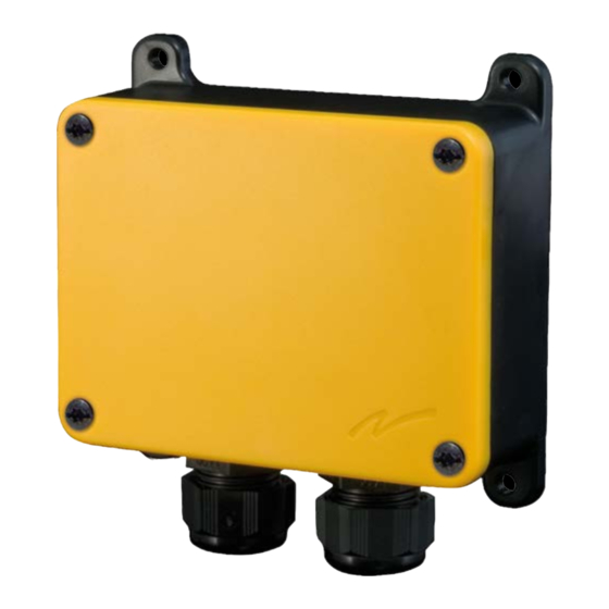
Chapter 2: PRODUCT DESCRIPTION CHAPTER 2: PRODUCT DESCRIPTION WARNING! The receiver must NOT be opened by anyone other than a qualified installer. Make sure that the electricity is switched off before opening the receiver. BASE BOARD NOTE! This base board is fitted in the following receiver models: PN-R8-1, PN-R8-6, PN-R8-10, PN-R8-11 ... -
Page 6: Terminal Block For Input Power
x Radio transmission established. yellow x Receiving a radio packet from a transmitter other than a Panther. yellow x Receiving a radio packet from a transmitter set to the radio mode different green from that of a receiver. -
Page 7: Error Codes
ERROR CODES If an error occurs that requires the attention of Tele Radio AB, all Function LEDs will flash. At the same time, one or more Relay LEDs will light up. Note the Relay LEDs that light up and contact your representative for assistance. -
Page 8: Placement Of Antenna
PLACEMENT OF ANTENNA NOTE! For optimum performance, place well away from metal objects such as metal girders, high- voltage cables and other antennas. Antenna with cable – the cable allows the antenna to be posi- tioned freely and high above the ground. ... -
Page 9: Chapter 3: Installers' Guide
Chapter 3: INSTALLERS' GUIDE CHAPTER 3: INSTALLERS' GUIDE RADIO MODE NOTE! The radio mode is determined by the selected Operating mode. To establish a radio link between the transmitter and receiver, both units need to be set to the same radio mode. ... - Page 10 Chapter 3: INSTALLERS' GUIDE 1. Press the Function button twice. LED 8 lights (yellow). The relay LEDs light (red). 1. Press the Function button twice. LED 9 lights (yellow). The relay LEDs light (red). 2. Press the Select button to enter the settings menu for switching relay functionality. The relay LEDs flash (red) to indicate that a latching or momentary functionality can be set to the corresponding relays.
-
Page 11: Operating Modes
OPERATING MODES Select Operating mode NOTE! Go to the Operating modes pages to see the Operating modes available when transmitting in continuous/discontinuous radio mode. Operating modes do not work for both radio modes. 1. Press the Function button 4 times. LED 10 lights (orange). - Page 12 OPERATING MODE 1 NOTE! Only for discontinuous mode. T13-3/6/8/10 T7-14/15/16 T19-2 T21-3/6/8/10 1 1 1 1 1 1 3 1 1 1 1 1 1 3 1 1 1 1 1 1 6 1 1 1 1 1 1 6 1 1 1 1 1 1 8 step step...
-
Page 13: Chapter 4: Guarantee, Service, Repairs And Maintenance
Chapter 4: GUARANTEE, SERVICE, REPAIRS AND MAINTENANCE CHAPTER 4: GUARANTEE, SERVICE, REPAIRS AND MAINTENANCE Tele Radio AB products are covered by a guarantee/warranty against material, construction and manufacturing faults. During the guarantee/warranty period, Tele Radio AB may replace the product or faulty parts. -
Page 14: Chapter 5: Regulatory Information
Chapter 5: REGULATORY INFORMATION CHAPTER 5: REGULATORY INFORMATION CE MARKING This product is in compliance with the essential requirements of directive 1995/5/EC of the European Parliament and of the Council. Latest version of the EC Declaration of Conformity can be downloaded from the Tele Radio AB website. -
Page 15: Chapter 6: Frequent Terms
Chapter 6: FREQUENT TERMS CHAPTER 6: FREQUENT TERMS Configuration ID Numerical code stored in both the transmitter and receiver unit. The receiver unit can only be controlled by a transmitter with the correct configuration ID. Continuous radio When in continuous radio mode the transmitter unit transmits continuously when mode it is switched on. - Page 16 This installation instruction is subject to change without prior notice. Download the latest installation instruction from www.tele-radio.com...
Need help?
Do you have a question about the PN-RX-MN5 and is the answer not in the manual?
Questions and answers