Advertisement
W I C H T I G E R H I N W E I S ! ! !
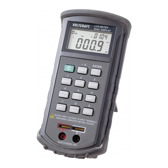
LCR HANDMESSGERÄT 4080
Best
.-Nr. 12 09 82
Nachtrag
zu
Punkt
D6
Bedienungsanleitung
Sehr geehrte Kundin, sehr geehrter Kunde,
bei
der
Messung
von
Widerstandswert angezeigt, der sich auf den Gesamtwiderstandswert
R der Spule bezieht. Das bedeutet :
Gleichspannungswiderstand plus Verlustwiderstand.
Um
den
Verslustwiderstand
Gleichstromwiderstand,
gemessen von einem Multimeter (mit
Gleichspannung), vom angezeigten R-Wert abziehen.
Wir bitten um Beachtung.
Ihr
Taster
Q/D/R
Seite
Spulen
wird
vom
Messgerät
zu
ermitteln
muss
Voltcraft-Team
W I C H T I G E R H I N W E I S ! ! !
W I C H T I G E R H I N W E I S ! ! !
UPGRADE
11
der
ein
man
den
UPGRADE
Stand: 01/09
Stand: 01/09
Advertisement
Chapters

Related Manuals for VOLTCRAFT LCR 4080


Summary of Contents for VOLTCRAFT LCR 4080
- Page 1 Gleichstromwiderstand, gemessen von einem Multimeter (mit Gleichspannung), vom angezeigten R-Wert abziehen. Wir bitten um Beachtung. Voltcraft-Team W I C H T I G E R H I N W E I S ! ! ! UPGRADE Stand: 01/09...
- Page 2 R der Spule bezieht. Das bedeutet : Gleichspannungswiderstand plus Verlustwiderstand. Verslustwiderstand ermitteln muss Gleichstromwiderstand, gemessen von einem Multimeter (mit Gleichspannung), vom angezeigten R-Wert abziehen. Wir bitten um Beachtung. Voltcraft-Team UPGRADE Stand: 12/08 UPGRADE Stand: 01/09 LCR HANDMESSGERÄT 4080 Best .-Nr. 12 09 82...
- Page 3 Gleichstromwiderstand, gemessen von einem Multimeter (mit Gleichspannung), vom angezeigten R-Wert abziehen. Wir bitten um Beachtung. Voltcraft-Team W I C H T I G E R H I N W E I S ! ! ! UPGRADE Stand: 01/09 LCR HANDMESSGERÄT 4080 Best .-Nr.
- Page 4 Messung Spulen wird Messgerät Widerstandswert angezeigt, der sich auf den Gesamtwiderstandswert R der Spule bezieht. Das bedeutet : Gleichspannungswiderstand plus Verlustwiderstand. Verslustwiderstand ermitteln muss Gleichstromwiderstand, gemessen von einem Multimeter (mit Gleichspannung), vom angezeigten R-Wert abziehen. Wir bitten um Beachtung. Voltcraft-Team...
- Page 5 à une tierce personne. © Copyright 2002 by Conrad Electronic GmbH. Printed in Germany. Gardez ce mode d’emploi pour toute consultation ultérieure ! Multimètre LCR 4080 Imprint Vous trouverez une liste des éléments contenus dans l’index page 47...
-
Page 6: Einführung
Einführung Sehr geehrter Kunde Mit dem LCR - Meßgerät 4080 haben Sie ein Komponentenmeßgerät nach dem neuesten Stand der Technik erworben. Das LCR – Meßgerät 4080 wurde in Anlehnung an die DIN VDE 0411, Teil 1 gebaut. Es ist EMV-geprüft und entspricht somit den Anforderungen der geltenden europäischen und nationalen Richtlinien. -
Page 7: Bestimmungsgemäßer Einsatz
200 H ±(1,0%+5dgts) 10 mH ouvert Bestimmungsgemäßer Einsatz des LCR – Meß- (open) gerätes 4080: 2000 H non spécifié 100 mH Messung von unipolaren oder bipolaren Kondensatoren (C) von ca. 5 pF bis 22.uH = micro-Henry = 10 exp. -6; mH = milli-Henry = 10 exp. -3; H = Henry = max. - Page 8 10 Taster "REL" für die Bezugswertmessung pour 120 Hz 200 nF ±(0,7%+5dgts) 10 pF ouvert 11 Taster "Hi / Lo" für die Einstellung der Ober – und Untergrenze in Verbin- de fréquence 2 uF ±(0,7%+3dgts) 100 pF dung mit dem Taster "SET" de test 20 uF ±(0,7%+3dgts)
-
Page 9: Table Of Contents
La mise hors circuit automatique s’en- 1 kHz Anzeigesymbol für die Meßfrequenz 1 Kilohertz suit au bout d’environ 10 minutes de non 120 Hz Anzeigesymbol für die Meßfrequenz 120 Hertz utilisation. Rallumez à l’aide de la touche L C R Anzeigesymbole für die Messung der Induktivität "L"... - Page 10 - Das Meßgerät ist gemäß DIN 57 411 Teil 1/VDE 0411 Teil 1, Schutzmaß- acoustique retentit (pour env. 2 sec.). Un changement de fusible est absolu- nahmen für elektronische Meßgeräte, gebaut und geprüft und hat das ment nécessaire. Procédez de la manière suivante : Werk in sicherheitstechnisch einwandfreiem Zustand verlassen.
-
Page 11: Vorstellung
Pour le nettoyage de l’appareil ou de la fenêtre de l’écran (display), n’utilisez - Wenn anzunehmen ist, daß ein gefahrloser Betrieb nicht mehr möglich ist, qu’un chiffon propre, sec, antistatique et non pelucheux. so ist das Gerät außer Betrieb zu setzen und gegen unbeabsichtigten Betrieb zu sichern. - Page 12 Tasters (ca. 2 s lang) die sog. Auto – Power – Off – Funktion (kurz APO, siehe En achetant ce multimètre LCR 4080 vous avez fait l’acquisition d’un produit Anzeige links oben) deaktivieren. Dadurch wird das Meßgerät nach ca. 10 correspondant aux derniers progrès de la technique.
- Page 13 retentit. Une valeur en pourcentage de "- 67,67 %" apparaît sur le Regel wendet man bei hohen Impedanzen den Modus "PAR" an, bzw. bei petit affichage. Le condensateur mesuré est de 67,67 % au-des- niedrigen Impedanzen den Modus "SER" entsprechend. sous de la valeur préréglée de 30 µF.
- Page 14 bedeutet festhalten eines Meßwertes. Die Funktion ist vor allem bei sich Appuyez pendant l’opération de mesure sur la touche "TOL". Le sym- ändernden Meßwerten sinnvoll. Die Messung wird auf Tastendruck angehal- bole "AUTO" pour la sélection de plage automatique disparaît. A sa ten, der letzte Meßwert und das Symbol "H"...
- Page 15 "SET". La valeur préréglée (par ex. 01,13 µF) sera indiquée. Attachez le D9 Taster "SET" condensateur électronique ELKO aux pinces en respectant la bonne Für die Unterfunktionen Open – (Offen) Kalibrierung, Short – (Kurzschluß) Kali- polarité, "00.00" sera indiqué. brierung, setzen von Hi / Lo Limits (Ober – und Untergrenzen), einstellen eines Toleranzbereiches (TOL) und einstellen eines Bezugswertes (REL) ist der Taster "SET"...
- Page 16 Nach erfolgter Einstellung der Obergrenze betätigen Sie den Taster chiffre, la position numérique suivante se met à clignoter. Après le "ENTER" (PAL SER zur Bestätigung) zur Einstellung der Untergrenze réglage de la limite supérieure, appuyez sur la touche "ENTER" (PAL (Pfeilsymbol "...
- Page 17 Si à la place de l’état normal "Out" apparaissait sur le petit affichage et talstelle usw. Nach erfolgter Einstellung des Bezugswertes betätigen "UAL" sur le grand affichage, le calibrage n’aurait pas réussi, les câbles Sie die ENTER – Taste zur Bestätigung und kehren automatisch zum de mesure sont éventuellement ouverts.
- Page 18 Achtung! La valeur "MAX" (=la plus haute valeur de mesure mesurée) sera d’abord affi- Bei hochohmigen Komponenten oder defekten Kondensato- chée et après un second actionnement de la touche, la valeur "MIN" (= la plus ren oder Spulen bzw. bei Überlauf (Overload ".OL") und bei basse valeur de mesure mesurée) sera affichée.
- Page 19 D6 Touche "Q/D/R" D12b) Toleranzmessung ohne Fixwerte Déterminez à l’aide de cette touche la fonction de qualité "Q" de votre bobine, Betätigen Sie während der Messung den Taster TOL. Das Symbol la valeur inversée de la fonction de qualité "D" de votre condensateur et la "AUTO"...
-
Page 20: Entsorgung
puter, ist beiliegend. Grundkenntnisse im Umgang mit einem PC werden aller- D2 "FREQ" Réglage de la fréquence de test ou aussi de la fréquence de dings vorausgesetzt. mesure Avec cette touche on règle la fréquence de mesure 120 Hz ou 1 kHz. Selon le a) Anschluß... -
Page 21: Wartung Und Kalibrierung
Tenez compte avant chaque connexion de l’état des prises jack et des bornes wie Sie einige dieser Störungen relativ leicht selbst beheben können; Beach- du multimètre et veillez à ce que l’isolation ne soit pas endommagée. ten Sie unbedingt die Sicherheitshinweise! Fehler Mögliche Ursache B Installation du multimètre (position inclinée) - Page 22 durch eine unverbrauchte gleichen Typs. Nach erfolgtem Batteriewechsel - N’utiliser pour les opérations de mesure que les câbles de mesure conte- legen Sie die Batterie in das Batteriefach und verschließen Sie dieses wieder nus dans l’emballage. Seuls ces câbles sont autorisés. sorgfältig.
-
Page 23: Technische Daten Und Meßtoleranzen
- L’instrument de mesure a été construit et contrôlé selon les normes EN Technische Daten und Meßtoleranzen 61010-1, pour appareils de mesure électroniques et a quitté l’usine de pro- duction dans un état irréprochable du point de vue de la sécurité tech- A Technische Daten nique. - Page 24 B Meßtoleranzen Symbole pour la tolérance en [%] Angabe der Meßtoleranzen Cx in ± (% der Ablesung + Anzahl der 1 kHz Symbole pour la fréquence de mesure 1 Kilohertz Digits=Digitalstellenfehler) 120 Hz Symbole pour la fréquence de mesure 120 Hertz L C R Symbole pour la mesure de l’inductance "L"...
- Page 25 Touche "SET" pour le mode de réglage des fonctions "Hi/Lo" (au-delà et uH = micro-Henry = 10 exp. -6; mH = milli-Henry = 10 exp. -3; H = Henry = As/V au-dessous d’une valeur limite réglée), "REL" (mesure de valeur de réfé- Bei der Toleranz muß...
-
Page 26: Introduction
Restrictions d’utilisation du multimètre LCR 4080 : Introduction Mesure de condensateurs unipolaires et bipolaires (C) d’environ 5 pF jusqu’à Dear customer, max. 20000 uF = 20 mF with the LCR measuring instrument 4080 you have acquired a state-of-the-art Mesure de résistances (R) jusqu’à max. 10 MOhm component measuring instrument. -
Page 27: Prescribed Use
Measuring inductors (L) up to 20000 H Le multimètre LCR 4080 a été construit d’après les normes EN 61010-1. Il a été contrôlé d’après les directives de CEM et est ainsi conforme aux It is not admissible to carry out measurements in wet rooms or outdoors or exigences européennes et nationales en vigueur. - Page 28 2000 mH ±(0.7%+5dgts) 100 µH >2 sec HOLD" button for the background lighting and/or the hold- 20 H ±(0.7%+5dgts) 1 m H function (freezes the measured value) "MIN MAX" button for the maximum value - (MAX), 200 H ±(1,0%+5dgts) 10 mH open the minimum value –...
-
Page 29: Table Of Contents
B Measuring tolerances Display symbol for the hold-function Indication of the measuring tolerances Cx in ± (% of the reading + number of Display symbol for the setting mode digits = digit error) Display symbol for measuring relative to a reference value Display symbol for tolerance value measuring Display symbol for the parallel mode (parallel connection) Type... -
Page 30: Safety Instructions
Safety Instructions Technical Data and Measuring Tolerances A Technical Data Any claims for guarantee will become invalid in the event of damage that Display ........: two 4 digit displays up to 19999 with sym- results from the non-observance of the operating manual. We do not accept bol display and measuring units responsibility for such damage nor for any indirect losses. -
Page 31: Presentation
Insert the new battery into the battery compartment and close it carefully. - For your own safety you should absolutely avoid that the measuring instru- Make sure that the lead (red/black) of the terminal clip is not kinked. ment or the leads get humid or wet. - Only use the enclosed measuring leads for measuring. -
Page 32: Description Of The Function And The Buttons
Description of the Function and the Buttons You should absolutely observe the safety instructions! A Connecting the measuring lead Problem Possible cause Only use the enclosed measuring leads for any measurement. No display, instrument Is the battery low? Before every connection, check the connectors or measuring terminals and switched on ensure faultless insulation. -
Page 33: Disposal
E Using the LCR – Measuring in connection with a computer D2 "FREQ" button: setting of the test or measuring frequency. A Windows software for Windows ’98 and above, including the respective With this button, you can set the measuring frequency to 120 Hz or 1 kHz. interface lead for the connection/ communication with a computer, is After the setting, the respective symbol appears in the top right corner of the enclosed. - Page 34 D6 "Q/D/R" button measured value (e.g. 34.58µF) will be compared to the pre-set reference val- ue. The difference is more than 1%. So there will be an acoustic signal (6 x With this button you can establish the quality "Q" of your inductor, the recip- beep) to indicate that the difference is more than 1%.
- Page 35 If the value of the component is within the pre-set limits, both arrow symbols When you press the button once again, the difference of MAX minus MIN will are visible – not flashing. be displayed, when you press it the next time, the average value AVG will be displayed. For leaving the function, simply press the "HI / Lo LIMITS”...
- Page 36 D9 c) For setting a high and low limit (Hi) and (Lo), press the "RANGE” but- D9 e) For setting a reference value for measuring relative to a reference val- ton before you enter the set mode to set the desired measuring range ue (REL), press the "RANGE”...
Need help?
Do you have a question about the LCR 4080 and is the answer not in the manual?
Questions and answers