
Related Manuals for Brainchild VR06


Summary of Contents for Brainchild VR06
- Page 1 User Manual Paperless Recorder VR06 UMVR061D Brainchild Electronic Co., Ltd. 4th Edition, 10/2013...
-
Page 2: Table Of Contents
Page Contents Safety --------------------------------------------------------------------------------- Safety Symbols -------------------------------------------------------------------------- Safety Notes and Precautions ---------------------------------------------------------- Static Electricity ----------------------------------------------------------------------- 1. General Description -------------------------------------------------------------------- 1.1 Unique Features of Recorder ------------------------------------------------------- 1.2 Expandable Input and Output cards ------------------------------------------------ 1.3 Communication ------------------------------------------------------------------------ 1.4 Storage Media CF card ----------------------------------------------------------------- 1.5 Data Security -------------------------------------------------------------------------- 1.6 Infrared Detector --------------------------------------------------------------------- 1.7 Ordering Codes and Accessories --------------------------------------------------... - Page 3 4.8 System Info ------------------------------------------------------------------------------ 4.9 A Configuration Example ---------------------------------------------------------------------- 5. PC software and Communication configuration ---------------------------- 5.1 Observer I & Observer II PC software guide ------------------------------------- 5.2 Ethernet Configuration ------------------------------------------------------------ 61 5.3 RS 232, RS485, RS422 Configuration ------------------------------------------------------- 65 5.4 CF card Configuration --------------------------------------------------------------- 5.5 Configuration in Real-Time Viewer ----------------------------------------------------- 5.6 DDE dynamic data exchange ---------------------------------------------------- 6.
-
Page 4: Safety
The protection provided by the recorder may be impaired if it is used in a manner inconsistent with its intended purpose, or in an environment that exceeds the specifications of the recorder. Brainchild Electronic Co., Ltd. is not liable for customer’s failure to comply with these requirements. -
Page 5: Static Electricity
6. When cleaning the recorder, handle carefully and use soft dry cloth. Avoid the use of abrasives or any sharp and hard objects, which would damage the display. 7. Do not operate the recorder if any part has been removed or disassembled. Consult your nearest dealer at once. -
Page 6: General Description
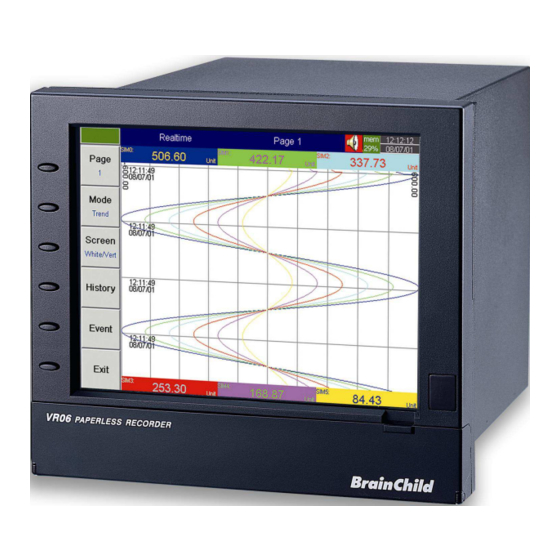
1. General Description 1.1 Unique features of recorder The VR06 is a well-designed paperless recorder with many outstanding features including: • 6.4〞TFT Color LCD with VGA Display in 640x480 pixels. • 6 isolated Analog Inputs in maximum • Plug & play I/O cards for easy expansion •... -
Page 7: Storage Media Cf Card
1.4 Storage Media CF Card The Solid Compact Flash Memory Card (CF card) 2GB capacity is a free standard storage media used for this instrument. Its compact size, anti-dust and anti-vibration features increase its reliability. To read measured data on CF Card, add a CF reader on USB port of PC. If the recorder is used with 6-channel inputs, an easy chart to show the maximum days CF can store the data. -
Page 8: Ordering Codes And Accessories
Ordering codes VR06 – □□□□ – □□□ – □□□ 1 2 3 4 – 5 6 7 – 8 9 10 Power 4: 90-250 VAC, 47-63 Hz 5: 20-28 VAC, 47-63 Hz 6: 11-18 VDC 7: 18-36 VDC 8. 36-72 VDC... - Page 9 Storage Media 6: 2 GB CF card Case/Mounting 4: standard panel mounting, black case 5: Bench top / portable style with handle, USA power cable, black case 6: Bench top with handle, European power cable, black case 10 Special Option: 0: none 1: 24VDC auxiliary power supply ( for transmitter, 6 channels ) 2: 3-channel current output...
- Page 10 The basic PC software Observer I is supplied free together with recorder. There is an additional charge for the extensive PC software Observer II supplied with communication of RS-232/422/485 or Ethernet. ◆ The Ordering Code of standard model without any option is VR06-4X00-011-640. The standard color of housing is made in black.
-
Page 11: Specifications
1.8 Specifications Power 90-250VAC, 47-63Hz, 60VA, 30W maximum 11-18VDC or 18-36 VDC, 60VA, 30W maximum Display 6.4〞TFT LCD, 640X480 pixel resolution, 256 colors Memory 16MB storage memory on board Storage media: 2GB CF ( Compact Flash ) cards Analog Input Cards (AI181, AI182, AI183) Channels: AI181 ~ 1 channel, AI182 ~ 2 channels, AI183 ~ 3 channels Resolution: 18 bits Sampling Rate: 5 times/ second... - Page 12 (-328 ~ 1652 ˚F) PT100 -210 ~ 700 ˚C ±0.4 ˚C 1.3KΩ (DIN) (-346 ~ 1292 ˚F) PT100 -200 ~ 600 ˚C ±0.4 ˚C 1.3KΩ (JIS) (-328 ~ 1112 ˚F) -8 ~ 70mV ±0.05% 2.2MΩ -3 ~ 27mA ±0.05% 70.5Ω 0~1V -0.12 ~ 1.15V ±0.05%...
- Page 13 COMM Module (CM181) Interface: RS-232 (1 unit), RS-485 or RS-422 (up to 247 units) Protocol: Modbus Protocol RTU mode Address: 1-247 Baud Rate: 0.3~38.4 Kbits/sec. Measured data Bits: 7 or 8 bits Parity Bit: None, Even or Odd Stop Bit: 1 or 2 bits Standard Ethernet Communication Protocol: Modbus TCP/IP, 10 Base T Ports: AUI (Attachment Unit Interface) and RJ-45, Auto- detect capability...
-
Page 14: Installation And Wiring
2. Installation and wiring 2.1 Unpacking If any damage is found while unpacking, the user should contact the local representative at once. It is suggested that the special packaging is retained for possible future requirement. 2.2 Installation Remove stains from this equipment using a soft, dry cloth. Don’t use harsh chemicals, volatile solvent such as thinner or strong detergents to clean the equipment in order to avoid deformation. - Page 15 The right side Figure 2 - 2 Panel Cutout ( standard DIN size 138 mm x 138 mm ) Figure 2 - 3 Note: Do not over tighten mounting clamp screws that could result in distortion of the case. There is no mounting angle restriction.
- Page 16 Bench top / Portable style If the recorder is used for Bench Top or portable purpose, then the assembly Kit MK183B (two ears, one handle, two feet included) is required. Assemble as follows, Firstly, put the right ear FV-R on the right hand side of metal case, and slide it into the case by pushing in direction as shown in Figures 2-4 through Figure 2-8.
- Page 17 Figure 2 - 6 Figure 2 - 7 Figure 2 - 8...
- Page 18 Holding the handle so that the instruction side can be seen, pull the handle outward by both hands and put it in vertical position on the top of case. Then, slide the handle into both ears as Figure 2-9. Rotate the handle downward as Figure 2-10 &...
- Page 19 Figure 2 - 10 Figure 2 - 11...
- Page 20 Figure 2 – 12 Figure 2 – 13 Figure 2 – 14 Note: To change the bench top into panel mount. Disassemble kit MK183B (one handle, two feet, and two ears) in reverse of above, then fit the mounting clamps.
-
Page 21: Setup Input, Output & 24Vdc Power Supply Cards
2.3 Setup input, output & 24VDC power supply cards Analog input cards ( part numbers AI181, AI182, AI183 ) AI181, AI182, AI183 are analog input cards in 1, 2, 3 channels respectively. Each card includes universal input of TC ( J, K, T, E, B, R, S, N, L ), PT100, mV, mA, V. To select a specific input, first set jumpers and switches according to the sticker information on the card as Figure 2–15, and plug it into the rear slot then power on. - Page 22 Analog input card ( part number AI183V ) AI183V are analog input cards in 1, 2, 3 channels respectively. Each card includes linear input of ± 60mV, ± 20mA, ± 2V, and ± 20V only. To select a specific input, first set jumpers and switches according to the sticker information on the card as Figure 2–16, and plug it into the rear slot then power on.
-
Page 23: Wiring Of The Cards
2.4 Wiring of the cards Wiring Precautions 1. Care must be taken to ensure that maximum voltage rating specified on the label is not exceeded. 2. For the panel-mount version, it is recommended that near the equipment an external fuse and an external switch rated at 2A/250 VAC should be equipped. - Page 24 Analog input cards ( AI181, AI182, AI183 ) Figure 2 – 18 Analog input cards ( AI183V ) Figure 2 – 19 Digital output card ( DO181 ) Figure 2 – 20...
- Page 25 Digital input card ( DI181 ) Figure 2 – 21 Analog output card ( AO183I & AO183V ) Figure 2 – 22...
-
Page 26: Rs-232, Rs-422, Rs-485 Wiring
24 VDC auxiliary power supply card ( AP181 ) Figure 2 – 23 2.5 RS-232, RS-422, RS-485 wiring Figure 2 – 24... - Page 27 Figure 2 – 25 Figure 2 – 26...
-
Page 28: Installation Of Compact Flash Cf Card
2.6 Installation of Compact Flash CF card A 2GB Compact Flash Card is installed in each recorder. If a bigger capacity Compact Flash card is required, and the user decides to buy it locally, please check the brand name of CF card first. To be fully compatible, only one brand SanDisk is recommended. -
Page 29: Basic Operation
3. Basic Operation After installation and wiring, power on the recorder, six soft keys Page, Mode, History, Event, Status and Exit will appear on the left hand side of LCD display. Opening the plastic cover at the front of the recorder, the user may find another five soft keys Dump, Clear, Operate, Config and Shutdown. -
Page 30: Mode
Keep pressing Page key, you will get Page All to display all enabled channels. Figure 3 – 2 3.2 Mode Press Mode key to select the different ways of displays, which include Mix, Trend, Bar or Digital mode. Mix: The display default is Mix mode. Several modes including horizontal/ vertical trend, bar and digital modes can be mixed together. -
Page 31: History
3.3 History Press History key, to display historical trend. Press directional keys ← → to backward or forward. Press Zoom key to zoom in the time scale. The Zoom can be done variously in 1 sec/dot, 1 hour/Page, 12 hours/Page, 1 day/Page or 1 week/Page. Press Back key going back to the original display. Figure 3 –... -
Page 32: Event
3.4 Event Press Event key, the Event /Alarm List displays general Events, Alarms and Reports. Press Mode key to choose Evnt/Alam ( Event/Alarm ) or Report. Event/Alarm It displays the Ack (acknowledgement), Type, Source, Active time, Clear time and Value of events or alarms. -
Page 33: Status
Report Press Mode key to choose Report. This mode is only available after the option of Math. Counter, Totalizer & FDA 21 CFR part 11 was ordered before. It produces reports about Counters 1-6, Totalizers 1-18, AI1- AI06 MinMaxAve( Minimum, Maximum and Averaged values of analog inputs in certain period of time ), Math1-Math18 MinMaxAve and All CH MinMaxAve. -
Page 34: Dump
3.7 Dump Before removing the CF card from the recorder, it is necessary to press the Dump key to transfer the measured data and events from the internal memory of the recorder to the CF card 3.8 Clear If the internal memory goes down to 25%, the mem icon on the top right changes color from green to red. Also, when the internal memory reserved for events is down to 25 %, the evnt ( event ) icon on the top right changes color from green to red. -
Page 35: Small Icons
3.12 Small icons (on the top right side ): Figure 3 – 6 Buzzer: Appears by flashing in red whenever the alarm status occurs. The buzzer will disappear after the user acknowledges the alarm, and the process becomes normal. Evnt: The percentage of memory space left for events/alarms. For example, evnt 84% means 84% space left for events/alarms. -
Page 36: Configuration
4. Configuration Press the Config key to enter the Configuration mode. The following buttons appear: Channel, Display, Tools, Instrument, Clock, System Info and Demo. Meanwhile, the following soft keys appear at the bottom: Save, Load, Default and Back. Figure 4 – 1 Soft Keys Enter: First select the mode by pressing directional keys↑↓←... -
Page 37: Channel ( Analog Input, Digital Input, Analog Output, Math Input )
4.1 Channel ( Analog input, Digital input, Analog output, Math input ) Analog input After entering the Configuration mode, select Channel and press the Enter key to get into Channel mode. It displays the Analog input AI first. Press directional keys〈 〉at the bottom to select the channel. Afterwards, press directional keys ↑↓←... - Page 38 Log Speed: It is the logging speed (recording speed) of measured data. Select Log Speed column, then choose 1, 2, 5, 10, 30, 60 or 120 seconds. Offset: It is offset value to correct the sensor error. Gain: It is a multiplier to correct the sensor error. The correct value = ( the process value + offset ) x gain Sensor: It displays automatically the setup input of V, mV, mA, T/C ( J, K, T, E, B, R, S, N, and L ), PT100, and JPT100.
- Page 39 Operate key. The former is actuated by an event, and the latter is actuated by manual control, no event necessary. Various types of jobs can be selected: No Action: Do nothing. Log Alarm: Record alarms Log Event: Record events Stop logging: Stop logging data. Start logging: Start logging data.
- Page 40 Digital input Press DI key to select the Digital input. Define the name, Description, and set up the Event accordingly. Press directional keys〈 〉at the bottom to select the channel. Analog output Press AO key to select the Analog output. Define Output either 0-20mA or 4-20mA if it is current output card AO183I.
- Page 41 Math input Press Math key to select the Mathematics input. Except for Expression, it is similar to do the setting up for Analog input above. Define the name, Description, and select Type, Log Method, Log Speed, Unit, Scale Low, Scale High, and Event. Enter Expression column, it appears Source, Operator and a keyboard. The Source covers all available Analog inputs, Math inputs and Counters.
- Page 42 Math Expressions and an example Expressions on recorder Mathematics Functions Addition Subtraction Multiplication Division SIN(x) sin(x) COS(x) cos(x) EXP(x) SQRT(x) Square root of x LN(x) TG(x) tan(x) CTG(x) 1/tan(x) ASIN(x) ACOS(x) ATG(x) LOG(x) ABS(x) Absolute of x SQ(x) ROUND(x) The closest integral number to x HI(x,y) The bigger value between x and y LO(x,y)
-
Page 43: Display
4.2 Display Press the Back key to return to the beginning of the Configuration mode. Select Display and press Enter key to get into Display mode. Display may have a maximum 6 Pages and each Page may display maximum 6 channels. Figure 4 –... - Page 44 StatusBar: To make it convenient when viewing the status of Totalizer, Counter, DI or DO, the user may enable these items in the StatusBar. For example, after enable Totalizer 1〜6 and Counter 1〜6, two extra bars of Totalizers and Counters will appear at the lower part of display. Figure 4 –...
-
Page 45: Tools ( Timer, Counter & Totalizer )
4.3 Tools ( Timer, Counter & Totalizer ) Press Back key, to return to the beginning of Configuration mode. Select Tools, then press Enter key to get into Tools mode. Timer, Counter and Totalizer are defined here. Counter and Totalizer are available only if the options of Math, Counter &... - Page 46 An example of Timer & Report: A staff plans to get a daily report from the recorder about the minimum, maximum and average values of the process every day. He needs to get into Tools mode of Configuration and do the following settings. After the production has finished, he can press Event key on the left hand side, and press Mode key to select Report mode and get the report like Figure 4-7.
- Page 47 Counter Figure 4 – 8 Press directional keys〈 〉at the bottom to select one from 6 available counters. Name: Defines the name of counter. Desc: Defines the description for a specific counter on the display. Unit: Defines the unit of counter Preset: Defines the preset value for the counter.
- Page 48 Totalizer Figure 4 – 9 Press directional keys〈 〉at the bottom to select from 18 available totalizers. Name: Defines the name of the totalizer. Desc: Defines the description for a specific totalizer on the display. Source: Select a specific analog input or Math input to be used for totalizing. Action: Disables or enables the totalizer.
- Page 49 Setpoint: Defines the set point of process value to trigger the totalizer. Job1, Job2: various jobs as described in 4.1 Channel, 2 jobs for each totalizer. An example of Totalizer: A factory operates for 8 hours a day, and the staff wish to get the total volume of production from daily, weekly and monthly reports.
-
Page 50: Instrument
4.4 Instrument Press Back key, to return to the beginning of Configuration mode. Select Instrument then press Enter key to get into Instrument mode. Figure 4 – 10 Instrument Name: Assigns a name for the recorder in maximum 8 characters. Language: Languages of English, Chinese (simplified), Chinese (traditional), Japanese, Korean, French, German, Italian, Polish, Spanish, Russian, Czech and Thai are all available. - Page 51 Data Transfer: Select Dump and Clear if the user wishes to clear the data on recorder after dumping data to PC or CF card. Select Transfer and remain if the user wishes to remain the data on recorder after transferring data to PC or CF card. Keypad Sound: Selects the following four options: disable, minimum, medium or maximum LCD: Screensaver: To prolong the life of the LCD display, it is suggested to set the display turn-off time in 1,...
- Page 52 Ethernet: IP: Select Automation if the server on the network automatically allocates the IP address for the recorder. Select User Define to manually set a fixed address for the recorder. Two new columns will appear for keying in fixed addresses IP Address: Defines the correct address of the recorder on the network Subnet Mask: Defines the correct SubnetMask address on the network Default Gateway: Different Gateway has different IP address on Ethernet.
-
Page 53: Clock
4.5 Clock Press Back key, to return to the beginning of Configuration mode. Selects Clock then presses the Enter key to get into Clock ( Date/Time ) mode to set up the local time. Date Style: Selects either month/date/year or date/month/year Date/Time: Set up the local time. -
Page 54: Security & Fda 21 Cfr Part 11 Compliance
4.6 Security & FDA 21 CFR part 11 compliance In 4.4 Instrument, in column Security select Normal or higher security CFR-21. If the normal security is selected, for different users it needs just to key in a common password in maximum 8 characters. Once the password has been entered, the user needs to key in the password whenever Config, Dump, Clear or Operate soft keys are required. -
Page 55: Demo
Time of validity: If the Time of validity of any user been defined as 30, 60 or 90 days valid account, it means that the account will be closed after 30, 60 or 90 days. If it is defined as 30, 60 or 90 days valid password, then it will request the user to key in a new password, or remain the old one after 30, 60 or 90 days. -
Page 56: A Configuration Example
Boot ROM ver: It is version of Boot ROM. Memory (Free / Total): Indicates the percentage of free memory to total memory reserved on the recorder. 8 MB memory on board is reserved for storing measured data. A small icon on the top right indicates the percentage of free memory e.g.: mem 96 % . -
Page 57: Pc Software And Communication Configuration
5. PC software and Communication configuration 5.1 Observer I & Observer II PC software guide This is simple guide for PC software. Please refer more details to the software user manual in the HELP of PC software itself. Observer I & II are the PC software used for the recorder. Observer I contains two components Observer II contains three components CONFIG_VIEWER is for configuration of the recorder from PC. - Page 58 Uninstall Observer Software This is to remove Observer software from PC. Observer I or Observer II may be uninstalled from PC any time from the following two ways Control panel- Add/remove programs-observer I/observer II Start –Programs-Observer I / Observer II / Uninstall CONFIG_VIEWER This is used for configuration of the recorder from PC.
- Page 59 To set password Receive configuration (CF reader/RS 232/Ethernet) Send configuration (CF card/RS 232/Ethernet) If Observer software is already configured in the PC, then you can select *.prj file to open the project. For the first time configuration you can cancel the above window and select new project Enter the name of the project.
- Page 60 Bank This is used to select physical connection between the recorder and PC. Three options are available 1. CF card 2. Ethernet 3. RS 232 2GB CF card shall be supplied along with the recorder. Standard Ethernet port (RJ 45 female) shall be available at the recorder.
-
Page 61: Ethernet Configuration
5.2 Ethernet Configuration It is possible to use PC software Observer II for data logging from multiple units of recorders connected on standard Ethernet. Total number of devices that can be connected depends on the hardware interface selected for the application. For example, 255 hardware devices can be connected on Ethernet. Maximum 1024 tags can be configured at Observer II for data logging, archiving and analysis. - Page 62 Straight Through Crossover Cable Cable VR06-LAN/HUB VR06-PC/Notebook RJ-45 RJ-45 RJ-45 RJ-45 1 Tx+ 1 Rc+ 1 Rx+ 3 Tx+ 2 Tx- 2 Rc- 2 Rc- 6 Tx- 3 Rc+ 3 Tx+ 3 Tx+ 1 Rc+ 6 Rc- 6 Tx- 6 Tx- 2 Rc- 6.
- Page 63 Select Ethernet in the Bank by using radial button Open for Ethernet connection Enter the IP address of the Recorder System will ask “Do you want to receive configuration data now? (Y/N)” Click on “Yes” to upload the recorder configurations to PC.
- Page 64 If Upload is successful, it shows message as “Configuration successful” and all the configuration settings of the recorder now available at PC. The information includes all channel details of Input/Output cards as per Jumper/switch settings. If Upload is unsuccessful, it shown message as “No response from Recorder, connection fails”. If this is the case, please check the Ethernet cable connections at both the recorder and PC/LAN HUB side.
-
Page 65: Rs 232, Rs485, Rs422 Configuration
5.3 RS 232, RS485, RS422 Configuration It is possible to use PC software Observer II for data logging from multiple VR06 recorders connected on network RS 485. Total number of devices that can be connected depends on the hardware interface selected for the application. - Page 66 10. Click on “Yes” to upload the recorder configurations to PC. 11. If Upload is successful, it shows message as “Configuration successful” and all the configuration settings of VR06 recorder now available at PC. The information includes all channel details of Input/Output cards as per Jumper/switch settings.
- Page 67 If Upload is not success, it shown message as “No response from Recorder, connection fails”. If this is the case, please check the RS 232 cable connections at both the recorder and PC. Also make sure that green communication LED available for proper firm connection at back RS 232 port available at recorder back side.
- Page 68 It is important to check COM port of PC to see whether it been properly set. My computer-Properties-Hardware-Device Manager – Ports – COM 1 – Properties Devise usage: It should be enabled Device status: The device is working properly. If above conditions are not met, then RS 232 port is having problem at PC. Contact system administrator for replacing the port or updating driver properly.
- Page 69 Make sure that RS 232 communication setting at the recorder and PC are equal.
-
Page 70: Cf Card Configuration
5.4 CF card Configuration 1. If no other higher capacity CF card been ordered, the standard 2GB CF card shall be supplied along with the recorder. 2. Save configurations from recorder to CF card at Recorder. Configuration – Save. This step will make sure that all IO cards information as per jumper and Dip-switch selection will be saved in to the CF card. - Page 71 6. Select CF card using radial button 7. Click on to set CF path to receive the configuration data available in CF card. 8. Click on Yes to receive the configuration data from CF card to PC.
- Page 72 9. If Upload is successful, it shows message as “Configuration successful” and all the configuration settings of the recorder now available at PC. The information includes all channel details of Input/Output cards as per Jumper/switch settings. 10. If Upload is unsuccessful, it shown error message as “Configuration file does not exist”. This message indicates that configuration information is not available in the CF card.
-
Page 73: Configuration In Real-Time Viewer
5.5 Configuration in Real-Time Viewer Configuration data It is used to define the configuration of the recorder for Real-Time Viewer. Please note that the configuration of Real-Time Viewer can be redefined and independent to the configuration of recorder itself. Double click on channel in the above spreadsheet to show the following Modify tag data with email configuration. - Page 74 Select Send email option for the job as shown above. The Email on event will be received like this, Type:HiAlarm Source:AI1 ActiveTime:12/12/20059:49:59AM Value:23.8 Option Three options of Share, Email and Communication are to be defined. It is mainly to set email configuration and real time log speed.
- Page 75 Share: Share/do not share options are available for user selection. If share option is selected, then Observer data available in the computer can be shared from other computers. On selection of this share data, shared folder will be created in C:\Observer. For example, you have one recorder and wish to analyze historical data at different computer.
- Page 76 Bank: It is to modify the channel for communication between Recorder and Observer from Real- Time Viewer. Four banks are available. In each bank protocol options Disable, Modbus_RS232 and Modbus_TCP are available for user selection. This Bank is used for Real-Time Viewer only, which is different from the Bank used for recorder itself on Page 60.
-
Page 77: Dde Dynamic Data Exchange
5.6 DDE dynamic data exchange DDE link Dynamic Data Exchange (DDE) is a standard inter-application communication protocol built into Microsoft Windows operating systems and supported by many applications that run under Windows. DDE takes data from one application and gives it to another application. It allows Windows programs that support DDE to exchange data between themselves. - Page 78 If the MS Office is not installed in the PC, then you cannot open the excel file created as above procedure. Please contact your system administrator to install MS office software in the PC. Now try to open the file from the desktop created for using DDE application with the recorder through Observer software.
- Page 79 If any “Error” test appears in any cell of Excel, possible reasons is no data available at selected tag. Check the data availability at the recorder and Observer software for a particular tag. If any “NAME” text appears in the Excel file, it indicates that particular tag is not configured properly. Tag name may not available in Observer software.
- Page 80 DDE with third party applications Once the data is available at Excel at particular cell, then data can be exchanged with the third party applications like PLC, SCADA, and Visual Basic etc. If data is to be exchanged with PLC, then PLC programmer can write Visual basic macro in Excel from the following link Excel –...
- Page 81 Example 2 DDE link between Allen-Bradley SLC 5/03 PLC and Excel Task: Read a block of data (5 integers) from PLC to Excel Name of the Excel file = Reports.XLS Data Source: PLC, Starting address= N7:30 Target cells in Excel= A7 to A11 User RSLinx to configure PLC and DDE link DDE topic name in RSLinx= DDE_REPORTS Sub Block_Read()
- Page 82 2) System – Node – Select DDE server as data source 3) Name = VR06 (No gaps ) 4) Application = RealTime_Viewer 5) Topic = TagService 6) Check enable in the box. (This node should be selected) 7) Now open the data base 8) Create analog tag with all the details similar to the tag at the recorder.
-
Page 83: Application Examples
6. Application examples Example 1: Flow measurement A level has to be converted into a flow according to the following formula. Q ( calculated flow speed in liter per minute ) = 0.0072*h *60 h ( level range in mbar per second ) = 0 – 30 mbar In 4.1 Channel Mode of Configuration, set AI1 as follows, Name: Level 1 Desc: xxxxxx... - Page 84 By using analog output card AO 183I and GSM controller GSM8000, it is able to retrieve process values and get alarms from the recorder to your Mobile via SMS through GSM system. Hardware requirements 1. Paperless recorder VR06 2. Analog output card AO 183I 3. GSM 8000 controller (8 AI, 8 DI & 8 DO) Set up at paperless recorder Ex: RTD is connected at channel 1 in the recorder.
- Page 85 Enter Supervisor and Operator mobile numbers in GSM controller. These are the mobile numbers to which SMS message to be sent from the GSM controller. Select channel number1, set low scale for 4 mA = 0, set High scale for 20 mA = 100 Set Alarm levels, Low = 40 and High = 80 To know the process values in your Mobile Send SMS from mobile to GSM controller as follows...
-
Page 86: Trouble Shooting
7. Trouble shooting... -
Page 89: Faqs Frequently Asked Questions
8. FAQs frequently asked questions Q1: What is the maximum scale low and scale high values we can set in the recorder for the analog inputs and outputs? A1: The minimum low scales of analog input are various -19999, - 1999.9, - 199.99, - 19.999, -1.9999, -0.19999 depending on the position of the decimal point The maximum high scales of analog input are various 45536, 4553.6, 455.36, 45.536, 4.5536, 0.45536 depending on the position of the decimal point... - Page 90 Q6: What kind of security is available in recorder? A6: There are two kinds of security. The normal security offers a common password. The high security with FDA 21 CFR part 11 compliance is available from version 2.2 on both recorder and PC software Observer.
- Page 91 Q13: What is the product warranty period of time? How does the user handle the defective recorder? A13: It is 18 months after shipping from Taiwan. Contact your supplier once it becomes defective. Q14: How does the agent handle the defective recorder? What is the leadtime for the repairs? A14: To be cost effective, the agent is requested to verify and return the defective board according to the trouble shooting flow chart in the user manual.
- Page 92 Q21: How many recorders can be viewed in the Real-time Viewer of PC software Observer II? A21: Maximum 1024 tags can be viewed from the Real-time Viewer. These tags cover AI, Math, DI, DO, Counter and Totalizer, excluding AO. If each recorder is used with 6 tags in average, then the Real-time Viewer can view maximum 170 units of recorders.
- Page 93 Q27: Is it possible to print out the data in selected time from the recorder? A27: Please note that it is not possible to connect printer directly to the recorder. It is possible to print out the data in selected time from the Observer software. The printing data in Excel is available from the Historical Viewer of Observer software.
- Page 94 Q32: If I have some configuration problems, which files I have that to send to the supplier? A32: Both Recorder.cfg. and IO.dat. files in C:/Observer/Historical are required under this case. Q33: Does the recorder have an option to supply DC power supply to the transmitters? A33: The 24VDC auxiliary power supply card AP181 can offer the power to 6 pieces of transmitters.
- Page 95 Q38: I updated Observer software and recorder firmware to V 2.22 or above, DDE is not working properly with application of the third party. A38: From Observer 2.22 on, DDE format has been changed with the Tag name. For example, instead of Analog input1 AIn, now it becomes TAGn, which n stands for the number of channel.
- Page 96 Brainchild Electronic Co., Ltd. No. 209, Chung Yang Road, Nan Kang Dist., Taipei, Taiwan Tel: 886-2-27861299 Fax: 886-2-27861395 E-mail: sales@brainchild.com.tw Website: http://www.brainchild.com.tw...
Need help?
Do you have a question about the VR06 and is the answer not in the manual?
Questions and answers