Table of Contents
Advertisement
Quick Links
Advertisement
Table of Contents

Subscribe to Our Youtube Channel
Summary of Contents for CDH AMT AIRMASTER
- Page 3 INSTALLATION MANUAL The dehumidifier has been designed and produced to give many years of faultless operation, but like every mechanical system a correct installation and regular maintenance are vital. We reserve the right to change our products without prior notice. We can never be held responsible for any errors and/or omissions in this manual.
-
Page 5: Table Of Contents
Contents COMPOSITION HOUSING IDENTIFICATION LABEL COOLING CIRCUIT FANS FILTERS SWITCHBOARD CABINET WEIGHTS OPTIONS ACCESSORIES DIMENSIONS TRANSPORT AND UNPACKING GENERAL TRANSPORT UNPACKING REMOVING THE PALLET TRANSPORT SCREWS INSTALLATION DIRECTIONS GENERAL WORKING AREA CONDENSATION DRAIN WALL MOUNTING INSTALLATION ON THE FLOOR INSTALLATION EXAMPLE CONNECTIONS HOT WATER BATTERY General... - Page 6 ELECTRICAL DEFROST General Supply SWIMMING POOL CONDENSER General Hydraulic Connection Control OUTDOOR CONDENSOR General Composition Technical dates Control Cooling pipes ELECTRICAL DATA AND SUPPLIES POWER SUPPLY General Supply Automatic system CONTROLS SWITCHBOARD CABINET General Connection terminals Components Connection diagram PRINTING CIRCUIT BOARD START UP, SAFETY REGULATIONS AND MAINTENANCE START UP General...
- Page 7 FAILURES UNIT DOES NOT WORK UNIT RUNS CONTINUOUSLY UNIT WORKS BUT DOES NOT DEHUMIDIFY OR INADEQUATE OTHER FAILURES...
-
Page 9: Composition
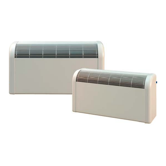
Combination of synthetic (PE) sides and zinc plate front and top panel, painted in textured RAL 9001 (other RAL- colours optional available Order code: see price list). Fitted with a curved anodised aluminium grate. Sound-absorbing and flame extinguishing 25 mm thick insulation (NEN-EN 13501-1:2002). Each unit bears a self-adhesive identification label on the small support on the left side in the unit. -
Page 10: Fans
One or two (on one deck mounted) directly driven fan(s) with a galvanized housing and wheel, with blades bent forward. Type of unit Number Air flow rate Current D4E 146-AA 07-36 400 m³/h 0,44 A D4E 146-AA 07-36 650 m³/h 0,44 A 92M-100 D4E 146-AA 07-36... -
Page 11: Options
OPTION RAL COLOUR Housing in a RAL-colour, different than the standard RAL 9001 colour. CLOSED FEET Set closed feet in zinc plate, standard painted in textured RAL 9001. OPTION RAL COLOUR CLOSED FEET Set closed feet in a RAL-colour, different than the standard RAL 9001 colour. WALL MOUNTING SET For vibration-free mounting of the unit against the wall. -
Page 12: Accessories
HYGROSTAT Wall mounted model: control of the dehumidifier HYGROSTAT CONNECTION TO SEVERAL UNITS To be used when several AMT units are installed in the same room. HYGROTHERMOSTAT Wall mounted model: control of dehumidifiers with heating HYGROTHERMOSTAT CONNECTION TO SEVERAL UNITS To be used when several AMT units with heating are installed in the same room MINIMUM BUILT-IN THERMOSTAT Built-in thermostat for minimum temperature limitation or control of electrical defrost... -
Page 13: Dimensions
Type of unit (mm) (mm) (mm) ∅ ½” ∅ 22 ∅ ½” ∅ 15 ∅ 22 65-92M-100 1305 ∅ ½” ∅ 15 ∅ 22 140-142M 1505 B = L.P.H.W. C = coaxial condensor Y = condensation drain E = Electrical connections AMT 12_00... -
Page 14: Transport And Unpacking
The units are separately packed in cardboard boxes, on one pallet tied with tape. To prevent damage to the unit, it is recommended that the unit is transported to its final destination IN its packing. When the unit is stored temporarily, it must be stored in a dry place until transport to its final destination Smaller units can usually be moved by manpower and/or using a trolley. -
Page 15: Installation Directions
Supporting material must be sufficiently strong To prevent resonance, make best use of sound insulating material – see wall mounting kit. Fitting or attaching the unit to wooden floors or walls is not recommended. This requires special precautions (anti-rumble materials). -
Page 16: Wall Mounting
If you are mounting the unit against the wall, we advise following directions: leaving a clearance of minimum 20 cm (*) from the floor – thus assuring enough air flow at the suction side - and minimum 1 m from the ceiling, thus avoiding that the unit will re-suck its own dried air. ... -
Page 17: Installation Example
Installation with 1 AMT Installation with 2 AMT AMT 12_00... -
Page 18: Connections
GENERAL Type of unit 92M-100 140-142M Nominal output * Nominal flow Pressure loss 1,68 2,64 5,94 * At 80/60°C WT° and 20°C LT° Used to keep the ambient area to temperature or bring this to temperature depending on capacity. The hot-water battery (LPHW) is fitted on the pulse side of the unit. The connection of the LPHW is on the left of the unit. -
Page 19: Electrical Heating
GENERAL Type of unit 92M-100 140-142M Output 3 - 6 Used to keep the ambient area to temperature or bring this to temperature, depending on capacity of the heating resistors. Composed of reinforced resistors of 1, 1,5 or 2 kW RUS321 with ribs of galvanised steel. Including one-stage control with run-on delay on the fan and excess temperature protection. -
Page 20: Swimming Pool Condenser
GENERAL Makes sure that the unit will keep working at a higher ambient temperature than the standard value – see technical specifications – and discharges the surplus heat to the swimming pool water. HYDRAULIC CONNECTION If the unit is fitted with a swimming pool condenser, this must be connected via a bypass or a separate pump to the return circuit line from the filter installation. -
Page 21: Outdoor Condensor
GENERAL To be used when a swimming pool condenser offers no solution to the problem of excessive heat discharge. COMPOSITION several rows of copper pipes (3/8”), with pressed-on aluminium plates, in a housing of galvanized steel plate, epoxy varnished. ... -
Page 22: Electrical Data And Supplies
GENERAL All units are equipped with an electric switchboard cabinet with control circuit board, compressor relay and connection terminals. External control equipment should be ordered and installed separately. All controls are 24VDC and thus of the ultra low safety voltage type. The units are fully pre-wired and constructed to CE standard. -
Page 23: Switchboard Cabinet
THEY ARE THEREFORE NEVER OUR RESPONSIBILITY. COMPONENTS All components used – except the circuit board (CDH product) - are standard electrical components. They can be replaced easily thanks to their mounting on DIN rails. Equivalent types must replace the relays used. -
Page 24: Start Up, Safety Regulations And Maintenance
GENERAL As soon as the unit is installed according to the guidelines, the power can be connected. Before connecting the dehumidifier, the ambient temperature must be checked. This must be higher than 10°C so the unit can be provided with enough warm air to be able to defrost. Connect the unit manually by turning the HYGROSTAT to a lower value. -
Page 25: Safety Regulations
FROST The unit must be protected against frost. When currentless, the LPHW can freeze. PROTECTION VOLUME All units must be placed outside the protection volume as specified in European standards. UNITS THAT ARE PLACED INSIDE THE PROTECTION VOLUME, MUST BE CONNECTED TO AN ISOLATING TRANSFORMER OR BE DOUBLE INSULATED. Hygrostats, thermostats and similar connected to the circuit board (24 VDC) are the ultra-low safety voltage type and can be placed inside the protection volume. -
Page 26: Failures
Hygrostat adjusted too high Adjust hygrostat at normal value = 60% Check the hygrostat on its action. Hygrostat defective When defective, replace it. Before replacing the fuses, first determine the cause. 6.3 A glass fuse on PCB faulty: replace by a fuse of the same value. Check Glass fuses defective 230V exit on the PCB relay. -
Page 27: Other Failures
In cold weather, damp spots can form on the cold bridges. The hygrostat may Hygrostat set to normal value, not be turned down but this is not a good solution: the unit will work for too long. It is defective and damp spots appear. recommended that the cold bridges be insulated.
Need help?
Do you have a question about the AMT AIRMASTER and is the answer not in the manual?
Questions and answers