
Summary of Contents for TRAJAN SAW WORKS 1319
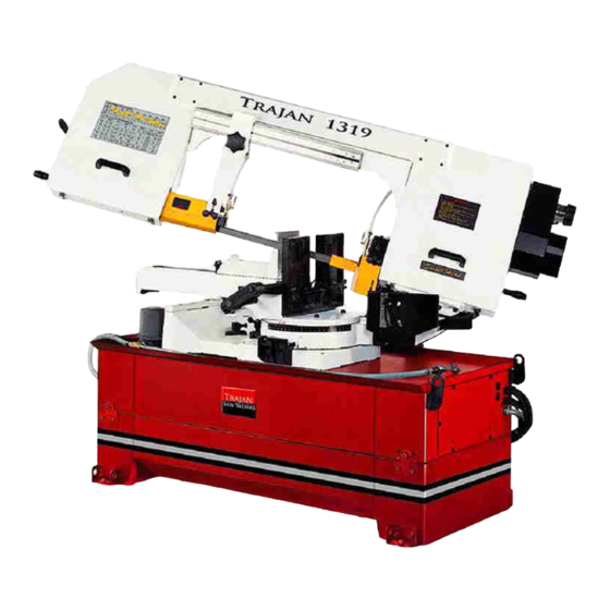
- Page 1 1319/1319A Metal Cutting Band Saw MODEL: 1319/1319A INSTRUCTION MANUAL...
-
Page 2: Table Of Contents
Before using this bandsaw, the proper electrical connections specific to this machine must be followed. Trajan Saw Works accepts no responsibility or liability for damages or injuries caused by improper electrical components... -
Page 3: Machineoverview
1. MACHINE OVERVIEW Saw Head Variable Blade Speed Operator Controls Drive Motor Chip Brush Vise Assembly Miter Protractor Machine Base... -
Page 4: Safety
2. SAFETY A) OPERATOR SAFETY: 1. WEAR PROPER APPAREL. Avoid loose fitting clothing, jewelry & gloves 2. ALWAYS WEAR EYE PROTECTION 3. NEVER LEAVE THE SAW RUNNING UNATTENDED. TURN POWER OFF. 4. DO NOT OPERATE THE SAW UNDER THE INFLUENCE OF DRUGS, ALCOHOL, OR ANY PERSCRIPTION MEDICATION 5. - Page 5 12. REMOVE ADJUSTING KEYS AND WRENCHES. Form a habit of checking to see that keys and adjusting wrenches are removed from tool before turning it "on". 13. DON'T FORCE THE SAW. It will do the job better and be safer at the rate for which it was designed.
- Page 6 such as blades, bits, cutters, etc. 4. MAKE SURE that blade tension and blade tacking are properly adjusted. 5. RE-CHECK blade tension after initial cut with a new blade. 6. CHECK COOLANT DAILY Low coolant level can cause foaming and high blade temperatures.
-
Page 7: Machine Specification
3.SPECIFICATIONS MOTOR 60Hz 98 ~ 393 FPM Saw Blade Speed Variable Speed 50Hz 81 ~ 327 FPM Blade Size(mm) 27x0.9x3810 Dimension LxWxH (mm) 2030x700x1100 N.W / G.W (kgs) 550 / 600 Packing Measurement 2223x990x1150 Sets per 20’ CTNR 10 sets (mm/inch) 330 / 13 “... -
Page 8: Transportation & Installation
5.TRANSPORTATATION & INSTALLATION 5-1.Unpacking 1. Transportation to desired location before unpacking; use powered lifting jack. (Fig. B) 2. Transportation after unpacking; please use heavy duty fiber straps to lift the machine. Fig. B ALLWAYS KEEP PROPER FOOTING & BALANCE WHILE MOVING THIS MACHINE. -
Page 9: Minimum Room Space For Machine Operation
5-3.Installation (1) Always Keep proper footing & balance while moving this 470kgs machine. And only use heavy-duty fiber belt to lift the machine as per Fig. (A). (2) Hang the machine up, away from the floor, take away the 4 pads and assemble them on the auxiliary stand. -
Page 10: Make Proper Tooth Selection
7. PROPER TOOTH SELECTION For maximum cutting efficiency and lowest cost per cut, it is important to select the blade with the right number of teeth per inch (TPI) for the material being cut. The material size and shape dictate tooth selection. -
Page 11: Bi-Metal Speeds And Feeds
8. BI-METAL SPEEDS AND FEEDS These figures are a guide to cutting 4"(100mm) material (with a 314 Vari-Tooth) when using a cutting fluid. Increase Band Speed: 15% When cutting 1/4"(6.4mm) material (l0/l4 Vari-Tooth) 12% When cutting 3/4"(19 mm) material (6/10 Vari-Tooth) 10% When cutting 1-1/4"(32 mm) material(5/8 Vari-Tooth) 5% When cutting 2-1/2"... - Page 12 A-10 H-11,H-12,H-13 Stainless Steel 410,502 440C 304,324 304L 316,316L TELL TALE CHIPS Chips are the best indicators of correct feed force. Monitor chip information and adjust feed accordingly. Thin or powdered chips – increase feed rate or reduce band speed. Burned heavy chips –...
-
Page 13: Use Of Main Machine Parts
9.USE OF MAIN MACHINE PARTS 9-1.POWER SYSTEM AND CONTROL PANEL Before connecting your machine to an electrical power system, be sure the motor rotation is in the proper direction. We recommend that 1.5mm² fused with a 10 amp, dual element, time lag fuse, to be used to supply power to all machines regardless of their electrical rating. - Page 14 which contacts the rear arm (M) for shutting off the motor and coolant system. 9-3.ADJUSTING SAW HEAD LOWER STOP The downward travel of the saw head should be adjusted so that when the saw arm is in the bottom position, the teeth of the blade will not touch the table surface.
- Page 15 blade is tensioned correctly before checking or adjusting tracking. The blade is tracking correct when the back of the blade just lightly touches the wheel flanges of both wheels while the machine is running. If the blade is not touching the wheel flanges, tighten or loosen screw C (fig.
- Page 16 9-9.BLADE AND COOLING SYSTEM The use of proper cutting fluid is essential to obtain maximum efficiency from a band saw blade. The main cause of tooth failure is excessive heat build-up. This is the reason that cutting fluid is necessary for long blade life and high cutting rates. cutting area and blade wheels should be kept clean at all times.
- Page 17 1. Loosen grip (A) (fig. 16). Pull out the bar (B) (fig. 16) swing and hold the bar. 2. Push to turn the swivel base to desired angle. Fig.16 Refer to scale on (D) for degree. 3. Lock the grip (A), then start the cutting. The swivel range is from 60 degrees clockwise to 45 degrees counter-clockwise.
- Page 18 9-13.HYDRAULIC SYSTEM (OPTIONAL FOR 1PH) A). The hydraulic system on the 1319A consists of a hydraulic cylinder, which is operated by a needle valve. The saw frame is raised automatically by the hydraulic cylinder, and as this is done, oil passes to the underside of the piston.
-
Page 19: Maintaining
9-16. HOW TO OPERATE HYDRAULIC UNIT (FOR 330A) 1. This hydraulic unit is using (Esso,H15) oil. Change first oil after 50 hours use. Then change oil every 6 months after. 2. Run the hydraulic unit for at least 10 minutes before changing oil, this will let the oil flow smoother and easier to change. -
Page 20: Trouble Shooting
(a) Check all machine parts for proper adjustment and function. (b) Lubricate bearing worm, and worm shaft to avoid the wear. (4) Yearly Maintenance (a) Adjust table to horizontal position for accuracy. (b) Check electric cord, plugs, switch, at least once a year to avoid chance of electrical damage. - Page 21 Blade. 3. Vibrating work-piece. 3. Clamp work piece securely 4. Gullets loading 4. Use coarser tooth blade or brush to remove chips. Motor running too 1. Blade tension too high. 1. Reduce tension on blade. 2. Drive belt tension too high. 2.
-
Page 24: Parts Lists
13 Parts Lists...
Need help?
Do you have a question about the 1319 and is the answer not in the manual?
Questions and answers