Table of Contents

Related Manuals for Toro 74253CP


Summary of Contents for Toro 74253CP
-
Page 1: Side Discharge
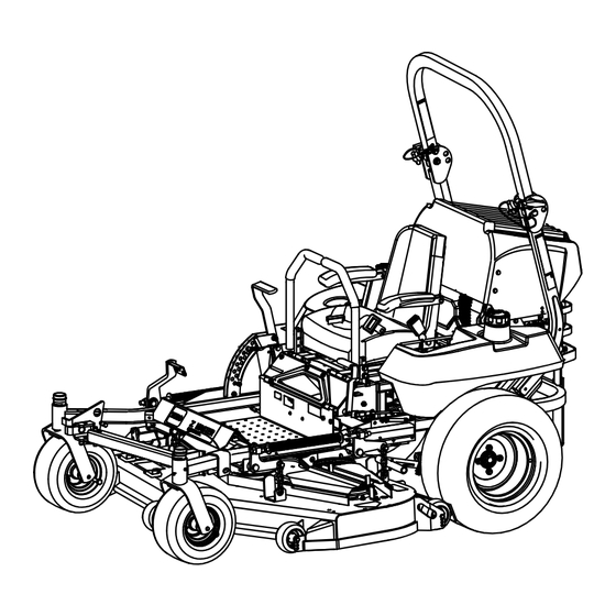
Form No. 3357-973 Rev C Z589 Z Master ® with a 60in or 72in TURBO FORCE Side Discharge ® Mower Model No. 74253CP—Serial No. 270000101 and Up Model No. 74254CP—Serial No. 270000101 and Up Register at www.Toro.com. Original Instructions (EN) -
Page 2: Table Of Contents
Figure 1 1. Model and serial number location Genuine Toro spark arresters are approved by the USDA Forestry Service. Important: This engine is equipped with a spark Model No. - Page 3 Using the Rollover Protection System Replacing the Mower Belt for 72in Mower (ROPS) ............15 Decks............. 44 Think Safety First ..........16 Adjusting the Mower Belt Tension for 72 inch Operating the Parking Brake ....... 17 Mower Decks ..........45 Starting and Stopping the Engine ......
-
Page 4: Safety
Safety • Use extra care when handling gasoline and other fuels. They are flammable and vapors are explosive. Improper use or maintenance by the operator or owner – Use only an approved container can result in injury. To reduce the potential for injury, –... -
Page 5: Slope Operation
• Be certain that the seat belt can be released quickly decals. in the event of an emergency. • Be aware there is no rollover protection when the • Use only Toro approved attachments. Warranty may roll bar is down. be voided if used with unapproved attachments. -
Page 6: Slope Chart
Slope Chart... -
Page 7: Safety And Instructional Decals
Safety and Instructional Decals Safety decals and instructions are easily visible to the operator and are located near any area of potential danger. Replace any decal that is damaged or lost. 58-6520 1. Grease 1-403005 66-1340 1-523552 65-2690 1-643253 68-8340 98-4387 1. - Page 8 98-5954 105-7798 107-1860 107-1613 107-1857 107-1861 107-1864...
- Page 9 107-2449 107-2102 108-5981 107-2112 110-2067 107-2114...
- Page 10 110-3853 1. Cutting/dismemberment 2. Remove the ignition key hazard, fan and and read the instructions 110-2068 before servicing or entanglement hazard, belt. performing maintenance. 1. Read the Operator’s Manual. 110-5772 1. Engine—stop 5. Continuous variable setting 2. Engine—run 6. Slow 3.
- Page 11 Manufacturer’s Mark 1. Indicates the blade is identified as a part from the original 110-6220 machine manufacturer. 110-6221 106-7492...
- Page 12 106-9989 107-9309 1. Warning—read the Operator’s Manual for information on charging the battery; contains lead; do not discard. 2. Read the Operator’s Manual. 110-0819...
-
Page 13: Product Overview
Hour Meter Product Overview The hour meter records the number of hours the engine has operated. It operates when the engine is running. Use these times for scheduling regular maintenance (Figure 4). Temperature Light The temperature light comes on when the engine is over heating (Figure 4). -
Page 14: Operation
Operation In certain conditions during fueling, static Note: Determine the left and right sides of the electricity can be released causing a spark machine from the normal operating position. which can ignite the gasoline vapors. A fire or explosion from gasoline can burn you and Adding Fuel others and can damage property. -
Page 15: Checking The Engine Oil Level
Important: Do not use fuel additives containing methanol or ethanol. Add the correct amount of gas stabilizer/conditioner to the gas. Note: A fuel stabilizer/conditioner is most effective when mixed with fresh gasoline. To minimize the chance of varnish deposits in the fuel system, use fuel stabilizer at all times. -
Page 16: Think Safety First
Important: Lower the roll bar only when absolutely necessary. 1. Remove the hairpin cotter pins and remove the two pins (Figure 7). 2. Lower the the roll bar to the down position. There are two down positions. See Figure 6 for the positions. -
Page 17: Operating The Parking Brake
Operating on wet grass or steep slopes can This machine produces sound levels in excess cause sliding and loss of control. of 85 dBA at the operators ear and can cause hearing loss through extended periods of Wheels dropping over edges can cause rollovers, exposure. -
Page 18: Starting And Stopping The Engine
Figure 12 Figure 10 1. Throttle—fast 2. Throttle—slow 1. Parking brake-ON 3. Brake Stop 2. Parking brake-OFF 6. Turn the ignition key to the Start position (Figure 13). When the engines starts, release the key. Starting and Stopping the Important: Do not engage starter for more than 5 seconds at a time. -
Page 19: Operating The Power Take Off (Pto)
Disengaging the PTO Important: Make sure that the fuel shut off valve is closed before transporting or storing To disengage, push the PTO switch to the off position the machine, as fuel leakage may occur. Set the (Figure 14). parking brake before transporting. Make sure to remove the key as the fuel pump may run The Safety Interlock System and cause the battery to lose charge. -
Page 20: Driving Forward Or Backward
the engine. While the engine is running, release the parking brake, engage the PTO and rise slightly from the seat; the engine should stop. 4. Sitting on the seat, engage the parking brake, move the PTO switch to off and move the motion control levers to neutral lock position. -
Page 21: Adjusting The Height-Of-Cut
2. Stop the engine, remove the key, and wait for all moving parts to stop before leaving the operating position. Children or bystanders may be injured if they move or attempt to operate the tractor while it 3. After adjusting the height-of-cut, adjust the rollers is unattended. -
Page 22: Adjusting The Flow Baffle
Figure 20 1. Cam lock 3. Rotate cam to increase or decrease locking pressure 2. Lever 4. Slot Figure 19 1. Anti-scalp roller 4. Flange Nut 5. Bolt 2. Spacer 3. Bushing Positioning the Flow Baffle The following figures are only recommendations for use. -
Page 23: Positioning The Seat
• Lowers the engine power consumption. lever • Allows increased ground speed in heavy conditions. • This position is similar to the benefits of the Toro 2. Slide the seat to the desired position and release SFS mower. lever to lock in position. -
Page 24: Unlatching The Seat
Pushing the Machine 1. Disengage the power take off (PTO) and turn the ignition key to off. Move the levers to neutral locked position and apply parking brake. Remove the key. 2. Rotate the by-pass valves counterclockwise 1 turn to push. This allows hydraulic fluid to by-pass the pump enabling the wheels to turn (Figure 27). -
Page 25: Breaking In A New Machine
Without the grass deflector, discharge cover, Driving on the street or roadway without turn or complete grass catcher assembly mounted signals, lights, reflective markings, or a slow in place, you and others are exposed to blade moving vehicle emblem is dangerous and can contact and thrown debris. -
Page 26: Using The Z Stand
Loading a unit onto a trailer or truck increases The machine could fall onto someone and the possibility of backward tip-over and could cause serious injury or death. cause serious injury or death. • Use extreme caution when operating the •... -
Page 27: Operating Tips
4. Set the foot of stand on the ground and rest the to thoroughly cut grass clippings, so do not set the latch on the pivot tab (Figure 30). height-of-cut so low as to totally surround the mower by uncut grass. Always try to have one side of the 5. -
Page 28: Blade Maintenance
Check the cutter blades daily for sharpness, and for any wear or damage. File down any nicks and sharpen the blades as necessary. If a blade is damaged or worn, replace it immediately with a genuine TORO replacement blade. -
Page 29: Maintenance
Maintenance Recommended Maintenance Schedule(s) Maintenance Service Maintenance Procedure Interval • Change the engine oil. • Check cooling system level. After the first 8 hours • Adjust the mower belt tension for 72 inch mower decks. • Check the hydraulic fluid. •... -
Page 30: Lubrication
If you leave the key in the ignition switch, someone could accidently start the engine and seriously injure you or other bystanders. Remove the key from the ignition before you do any maintenance. Lubrication Greasing and Lubrication Lubricate the machine when shown on the Check Service Reference Aid decal (Figure 32). - Page 31 1. Disengage the PTO, move the motion control levers to the neutral locked position, and set the parking brake. 2. Stop the engine, remove the key, and wait for all moving parts to stop before leaving the operating position. 3. Grease the idler pulley pivot (Figure 33). 4.
-
Page 32: Engine Maintenance
Engine Maintenance Contact with hot surfaces may cause personal injury. Keep hands, feet, face, clothing and other body parts away the muffler and other hot surfaces. Servicing the Air Cleaner Note: Check the filters more frequently if operating conditions are extremely dusty or sandy. Removing the Air Filter Service Interval: Every 250 hours (more often in dirty Figure 36... -
Page 33: Changing The Oil
Figure 37 Figure 38 Note: Using multi grade oils (5W-20, 10W-30, and 1. Muffler 3. Right side fuel cap 2. Dipstick 10W-40) will increase oil consumption. Check the oil level more frequently when using them. 6. Pull the oil dipstick and wipe the metal end clean Checking the Engine Oil Level (Figure 38). -
Page 34: Servicing The Spark Plug
Figure 41 1. Engine oil filter 3. Apply a thin coat of new oil to the rubber gasket on the replacement filter (Figure 42). 4. Install the replacement oil filter to the filter adapter. Figure 39 Turn the oil filter clockwise until the rubber gasket 1. - Page 35 Removing the Spark Plug 2. Check the gap between the center and side electrodes (Figure 44). Bend the side electrode (Figure 44) if 1. Disengage the PTO, move the motion control levers the gap is not correct. to the neutral locked position and set the parking brake.
-
Page 36: Fuel System Maintenance
Fuel System Maintenance Servicing the Electronic Fuel Injection System This machine contains an electronic fuel injection system. It controls the fuel flow under different operating conditions. Checking the Malfunction Indicator Light If the malfunction indicator light (MIL) illuminates, during operation, the electronic control unit (ECU) has Figure 45 detected a problem or fault in the direct fuel injection (DFI) system. -
Page 37: Electrical System Maintenance
Electrical System Maintenance Incorrect battery cable routing could damage the machine and cables causing sparks. Sparks can cause the battery gasses to explode, Servicing the Battery resulting in personal injury. • Always Disconnect the negative (black) Warning battery cable before disconnecting the positive (red) cable. -
Page 38: Servicing The Fuses
Important: Always keep the battery fully charged (1.265 specific gravity). This is especially important to prevent battery damage when the temperature is below 32°F (0°C). 1. Make sure the filler caps are installed in battery. Charge battery for 10 to 15 minutes at 25 to 30 amps or 30 minutes at 10 amps. -
Page 39: Drive System Maintenance
Drive System Maintenance Adjusting the Tracking The machine has a knob for adjusting the tracking located under the seat. Important: Adjust the handle neutral and hydraulic pump neutral before adjusting the tracking. Refer to Adjusting the Handle Neutral in Controls System Maintenance , page 47 and Adjusting the Hydraulic Figure 49 Pump Neutral in Hydraulic System Maintenance ,... -
Page 40: Checking The Tire Pressure
Checking the Wheel Hub Slotted Nut Service Interval: Every 500 hours The slotted nut needs to be torqued to 125 ft-lb (170 N-m). 1. Disengage the PTO, move the motion control levers to the neutral locked position and set the parking brake. -
Page 41: Servicing The Gear Box
3. Remove the dust cap from caster and tighten lock 6. Remove the right rear wheel from the machine. nut (Figure 53). 7. Locate the hole in the frame and remove the side 4. Tighten the locknut until the spring washers are flat plug in the gear box. -
Page 42: Cooling System Maintenance
Cooling System 1. Position the machine on a level surface, stop the engine, and set the parking brake. Maintenance 2. Unlatch the seat and tilt the seat up. 3. With the engine cool, check the overflow bottle level. Servicing the Cooling System The fluid needs to be up to the bump on the outside of the overflow bottle (Figure 55). -
Page 43: Brake Maintenance
Brake Maintenance Adjusting the Parking Brake Service Interval: Every 25 hours Every 200 hours 1. Engage the parking brake, lever up. 2. Measure the length of the spring. Measurement should be 2-1/2 inch (64 mm) between the washers (Figure 57). 3. -
Page 44: Belt Maintenance
Belt Maintenance Inspecting the Belts Service Interval: Every 100 hours Check the belts for squealing when the belt is rotating, blades slipping when cutting grass, frayed belt edges, burn marks and cracks are signs of a worn mower belt. Replace the mower belt if any of these conditions are evident. -
Page 45: Adjusting The Mower Belt Tension For 72 Inch Mower Decks
10. Install the idler spring to the two posts (Figure 59 and Figure 63). 11. Adjust the belt tension, refer to Adjusting the Mower Belt Tension. 12. Install the belt covers by sliding the cover into the tab, install the bolts, and close the latches (Figure 62). Figure 60 1. -
Page 46: Replacing The Pto Drive Belt
7. Rotate the ratchet or breaker bar to move the idler plate until the idler spring is between 10 and 10-1/4 inches (25.4 and 26.0 cm) from post to post as shown in Figure 63. 8. While holding the belt tension and spring length, tighten the idler plate bolts that secure the idler plate (Figure 63). -
Page 47: Controls System Maintenance
Controls System Note: Remove the PTO drive belt first if the pump drive belt needs to be replaced. Maintenance 1. Tilt the seat forward and remove the front engine panel. Adjusting the Control Handle 2. Remove the PTO drive belt. Neutral Position 3. -
Page 48: Hydraulic System Maintenance
Hydraulic System 9. Apply slight rearward pressure on the motion control lever, turn the head of the adjustment bolt Maintenance in the appropriate direction until the control lever is centered in the neutral lock position (Figure 68). Note: Keeping rearward pressure on the lever will Servicing the Hydraulic keep the pin at the end of the slot and allow the System... - Page 49 Important: Do not substitute automotive oil filter or severe hydraulic system damage may result. 3. Place drain pan under filter, remove the old filter and wipe the filter adapter gasket surface clean (Figure 70). Figure 69 1. Cap 3. Cold fluid level-full 2.
-
Page 50: Setting The Hydraulic Pump Neutral Position
12. Start the engine and let it run for about two minutes to purge air from the system. Stop the engine and check for leaks. If one or both wheels will not drive, Hydraulic fluid escaping under pressure can refer to Bleeding Hydraulic System. penetrate skin and cause injury. - Page 51 1. Raise the frame and block up the machine so drive wheels can rotate freely. 2. Disconnect the electrical connector from the seat safety switch. Temporarily install a jumper wire across terminals in the wiring harness connector. 3. Unlatch the seat and slide seat forward. 4.
-
Page 52: Mower Deck Maintenance
Mower Deck Maintenance Leveling the Mower at Three Positions Important: There are only three measuring positions needed to level the mower. Setting Up the Machine 1. Position mower on a flat surface. 2. Disengage the PTO, move the motion control levers to the neutral locked position and set the parking brake. - Page 53 Adjusting the Front-to-Rear Mower Pitch 1. Position the right blade front-to-rear (Figure 77). 2. Measure the right blade at the A location, from a level surface to the cutting edge of the blade tip (Figure 77). Figure 75 1. Measure here from blade 2.
-
Page 54: Servicing The Cutting Blades
File down any nicks and sharpen the blades as necessary. If a blade is damaged or worn, replace it immediately with a genuine Toro replacement blade. For convenient sharpening and replacement, you may want to keep extra blades on hand. -
Page 55: Removing The Blades
Blades must be replaced if a solid object is hit, if the blade is out of balance or is bent. To ensure optimum performance and continued safety conformance of the machine, use genuine TORO replacement blades. Replacement blades made by other manufacturers may result in non-conformance with safety standards. -
Page 56: Replacing The Grass Deflector
Installing the Blades 1. Install the blade onto the spindle shaft (Figure 83). Contact with a sharp blade can cause serious Important: The curved part of the blade must injury. be pointing upward toward the inside of the mower to ensure proper cutting. Wear gloves or wrap sharp edges of the blade with a rag. -
Page 57: Cleaning
Cleaning Important: The grass deflector must be able to lower down into position. Lift the deflector up to test that it lowers into the full down position. Cleaning Under the Mower Service Interval: Before each use or daily 1. Disengage the PTO, move the motion control levers to the neutral locked position and set the parking brake. -
Page 58: Storage
Storage Note: A fuel stabilizer/conditioner is most effective when mixed with fresh fuel and used at all times. Cleaning and Storage B. Run the engine to distribute conditioned fuel 1. Disengage the power take off (PTO), set the parking through the fuel system (5 minutes). brake, and turn the ignition key to Off. -
Page 59: Troubleshooting
Troubleshooting Problem Possible Cause Corrective Action Starter does not crank 1. Blade control (PTO) is engaged. 1. Move blade contro (PTO) to disengaged. 2. Parking brake is not on. 2. Set the parking brake. 3. Operator is not seated. 3. Sit on the seat. 4. - Page 60 Problem Possible Cause Corrective Action Uneven cutting height. 1. Blade(s) not sharp. 1. Sharpen the blade(s). 2. Cutting blade(s) is/are bent. 2. Install new cutting blade(s). 3. Mower is not level. 3. Level mower from side-to-side and front-to-rear. 4. Underside of mower is dirty. 4.
-
Page 61: Schematics
Schematics Wire Diagram (Rev. A) - Page 62 Notes:...
- Page 63 Spypros Stavrinides Limited Cyprus 357 22 434131 Surge Systems India Limited India 91 1 292299901 Hungary T-Markt Logistics Ltd 36 26 525 500 Toro Australia Australia 61 3 9580 7355 Toro Europe BVBA 32 14 562 960 Belgium 374-0102 Rev A...
- Page 64 Instructions for Obtaining Warranty Service The Toro® Company and its afliate, Toro Warranty Company, If you think that your Toro Product contains a defect in materials pursuant to an agreement between them, jointly promises to the or workmanship, follow this procedure: original purchaser* to repair any Toro Product used for normal 1.
Need help?
Do you have a question about the 74253CP and is the answer not in the manual?
Questions and answers