Table of Contents

Related Manuals for Toro 74385


Summary of Contents for Toro 74385
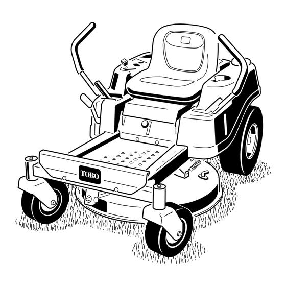
- Page 1 Form No. 3371-685 Rev B TimeCutter ® ZS 3200 Riding Mower Model No. 74385—Serial No. 312000001 and Up G015307 To register your product or download an Operator's Manual or Parts Catalog at no charge, go to www.Toro.com. Original Instructions (EN)
-
Page 2: Table Of Contents
You are responsible for operating the product properly and safely. Contents You may contact Toro directly at www.Toro.com for product and accessory information, help finding a dealer, or to register your product. Introduction..............2 Safety ................ -
Page 3: Safety
Safety Engine Maintenance..........26 Servicing the Air Cleaner ........26 Servicing the Engine Oil ........26 Safe Operation Practices Servicing the Spark Plug ........28 for Ride-on (riding) Rotary Cleaning the Blower Housing......29 Fuel System Maintenance ........30 Lawnmower Machines Replacing the In-line Fuel Filter ...... - Page 4 ◊ lack of awareness of the effect of ground – stay alert for humps and hollows and other conditions, especially slopes; hidden hazards; • Use care when pulling loads. ◊ incorrect hitching and load distribution. – Use only approved drawbar hitch points. Preparation –...
-
Page 5: Toro Riding Mower Safety
The following list contains safety information specific to • Follow the manufacturer's recommendations for Toro products or other safety information that you must wheel weights or counterweights to improve stability. know that is not included in the CEN standard. - Page 6 Uncertainty Value (K) = 1.1 m/s Measured values were determined according to the procedures outlined in EN 836. Whole Body Vibration Measured vibration level = 0.38 m/s Uncertainty Value (K) = 0.19 m/s Measured values were determined according to the procedures outlined in EN 836 (Riding &...
-
Page 7: Slope Indicator
Slope Indicator G011841 Figure 3 This page may be copied for personal use. 1. The maximum slope you can safely operate the machine on is 15 degrees. Use the slope chart to determine the degree of slope of hills before operating. Do not operate this machine on a slope greater than 15 degrees. Fold along the appropriate line to match the recommended slope. -
Page 8: Safety And Instructional Decals
Safety and Instructional Decals Safety decals and instructions are easily visible to the operator and are located near any area of potential danger. Replace any decal that is damaged or lost. 93-7009 114-1606 1. Warning—don't operate the mower with the deflector up or removed;... - Page 9 Battery Symbols Some or all of these symbols are on your battery 1. Explosion hazard 6. Keep bystanders a safe distance from the battery. 2. No fire, open flame, or 7. Wear eye protection; smoking. explosive gases can cause blindness and other injuries 3.
- Page 10 120-5468 1. Slow speed 2. Fast speed 120-2239 1. Warning—read the Operator's Manual. 5. Warning—do not use split ramps, use a full ramps when transporting machine. 2. Warning—read the instructions before servicing or performing 6. Loss of traction/control hazard, slopes—loss of traction/control maintenance;...
-
Page 11: Product Overview
121-0771 1. Choke 4. Slow 2. Fast 5. Power take-off (PTO), Blade control switch 3. Continuous variable setting Product Overview G017233 Figure 4 1. Footrest 5. Control panel 9. Deflector 13. Front caster wheel 2. Height of cut lever 6. Operator seat 10. -
Page 12: Ignition Switch
Smart Speed™ Control System Lever The Smart Speed™ Control System lever, located below the operating position, gives the operator a choice to drive the machine at two speed ranges, high and low (Figure 6). Figure 5 Control Panel 1. Throttle/Choke 3. -
Page 13: Operation
Operation Note: Determine the left and right sides of the machine from the normal operating position. Think Safety First Operating Safety Please carefully read all of the safety instructions and decals in the safety section. Knowing this information could help you, your family, pets or bystanders avoid injury. -
Page 14: Before Starting
• The blades are disengaged. DANGER • The motion control levers are in the park position. In certain conditions during fueling, static electricity can be released causing a spark which The safety interlock system also is designed to stop the can ignite the gasoline vapors. -
Page 15: Starting The Engine
Important: Do Not overfill fuel tank. Fill the expand. Overfilling may result in fuel leakage fuel tank to the bottom of the filler neck. The or damage to the engine or emission system. empty space in the tank allows the fuel to expand. 3. -
Page 16: Operating The Blades
Figure 13 1. Control panel 4. Off 2. Ignition key—run position 5. Run Figure 12 3. Ignition key—start position 6. Start 4. Fast 1. Control panel 2. Throttle/choke 5. Continuous variable lever—choke position setting 5. After the engine starts, move the throttle lever to 3. -
Page 17: Testing The Safety Interlock System
engine; the engine should not crank. Repeat with the other motion control lever. 3. While sitting on the seat, move the blade control switch to Off, and lock the motion control levers in the park position. Start the engine. While the engine is running, engage the blade control switch, and rise slightly from the seat;... - Page 18 1. Move the motion control levers to neutral and outward to the park position; disengage the blade control switch. WARNING Removing you hands from the motion control levers while the machine is in motion can result in a loss of control causing harm to you or bystanders.
-
Page 19: Stopping The Machine
Backward 1. Move the levers to the center, unlocked position. 2. To go backward, look behind you and down as you slowly pull the motion control levers rearward (Figure 19). Figure 20 1. Height-of-cut lever 3. 4.5 inch (115 mm), Transport position 2. -
Page 20: Adjusting The Motion Control Levers
Adjusting the Motion Control To Push the Machine Levers 1. Park the machine on a level surface and disengage the blade control switch. 2. Move the motion control levers outward to park Adjusting the Height position, stop the engine, and wait for all moving The motion control levers can be adjusted higher or parts to stop before leaving the operating position. -
Page 21: Grass Deflector
Grass Deflector The mower has a hinged grass deflector that disperses clippings to the side and down toward the turf. DANGER Without the grass deflector, discharge cover, or complete grass catcher assembly mounted in place, you and others are exposed to blade contact and thrown debris. -
Page 22: Operating Tips
Cutting a Lawn for the First Time Cut grass slightly longer than normal to ensure that the cutting height of the mower does not scalp any uneven ground. However, the cutting height used in the past is generally the best one to use. When cutting grass longer than six inches tall, you may want to cut the lawn twice to ensure an acceptable quality of cut. -
Page 23: Blade Maintenance
Check the cutter blades daily for sharpness, and for any wear or damage. File down any nicks and sharpen the blades as necessary. If a blade is damaged or worn, replace it immediately with a genuine Toro replacement blade. -
Page 24: Maintenance
Maintenance Note: Determine the left and right sides of the machine from the normal operating position. Recommended Maintenance Schedule(s) Maintenance Service Maintenance Procedure Interval • Check the safety interlock system. • Check the air cleaner for dirty, loose or damaged parts. •... -
Page 25: Lubrication
Lubrication 4. Connect a grease gun to each fitting (Figure 26 and Figure 27). Pump grease into the fittings until grease begins to ooze out of the bearings. Greasing the Bearings 5. Wipe up any excess grease. Service Interval: Every 25 hours—Grease all lubrication points. -
Page 26: Engine Maintenance
Engine Maintenance Replace a dirty, bent, or damaged element. Handle new elements carefully; do not use if the rubber seal is damaged. Servicing the Air Cleaner 4. Clean all air cleaner components of any accumulated dirt or foreign material. Prevent any dirt from Service Interval: Before each use or daily—Check the entering the carburetor. - Page 27 2. Disengage the blade control switch and move the motion controls outward to the park position. 3. Stop the engine, remove the key, and wait for all moving parts to stop before leaving the operating position. 4. Clean the area around the drain valve and on the machine frame.
-
Page 28: Servicing The Spark Plug
G014536 G005177 Figure 33 1. Oil filter 3. Adapter 2. Gasket 14. Slowly pour approximately 80% of the specified oil into the filler tube (Figure 30). 15. Install the oil fill cap/dipstick and push firmly into Figure 32 place (Figure 30). 1. -
Page 29: Cleaning The Blower Housing
Cleaning the Blower Housing To ensure proper cooling, make sure the grass screen, cooling fins, and other external surfaces of the engine are kept clean at all times. Annually or every 100 hours of operation (more often under extremely dusty, dirty conditions), remove the blower housing and any other cooling shrouds. -
Page 30: Fuel System Maintenance
Fuel System Maintenance DANGER In certain conditions, gasoline is extremely flammable and highly explosive. A fire or explosion from gasoline can burn you and others and can damage property. • Perform any fuel related maintenance when the engine is cold. Do this outdoors in an open area. Wipe up any gasoline that spills. -
Page 31: Electrical System Maintenance
Electrical System Maintenance Charging the Battery Removing the Battery WARNING Battery terminals or metal tools could short against metal machine components causing sparks. Sparks can cause the battery gasses to explode, resulting in personal injury. G005072 • When removing or installing the battery, do not Figure 37 allow the battery terminals to touch any metal parts of the machine. -
Page 32: Installing The Battery
Installing the Battery Drive System 1. Position the battery in the tray (Figure 37). Maintenance 2. Install the positive (red) battery cable to the positive (+) battery terminal using the fasteners removed Checking the Tire Pressure previously. Service Interval: Every 25 hours—Check tire pressure. 3. -
Page 33: Mower Maintenance
File down any nicks and sharpen the blades as necessary. If a blade is damaged or worn, replace it immediately with a genuine Toro replacement blade. For convenient sharpening and replacement, you may want to keep extra blades on hand. - Page 34 3. Measure from the tip of the blade to the flat surface here. Figure 42 1. Cutting edge 3. Wear/slot forming G009680 2. Curved area 4. Damage Figure 44 Checking for Bent Blades 1. Blade, in position for measuring 2. Level surface Note: The machine must be on a level surface for the 3.
-
Page 35: Removing The Blades
To ensure optimum performance and continued Installing the Blades safety conformance of the machine, use genuine Toro replacement blades. Replacement blades made by other 1. Install the blade onto the spindle shaft (Figure 47). -
Page 36: Leveling The Mower Deck
2. Install the blade stiffener, the curved washer (cupped G014630 side toward the blade) and the blade bolt (Figure 47). 3. Torque the blade bolt to 35-65 ft-lb (47-88 N-m). Leveling the Mower Deck Check to ensure the mower deck is level any time you install the mower or when you see an uneven cut on your lawn. - Page 37 Adjusting the Front-to-Rear Blade 8. Loosen the rear locking nut on the hanger bracket just enough to move the bracket (Figure 52). Slope Check the front-to-rear blade level any time you install G014633 the mower. If the front of the mower is more than 5/16 inch (7.9 mm) lower than the rear of the mower, adjust the blade level using the following instructions: 1.
-
Page 38: Removing The Mower
G014634 Figure 55 1. Adjusting rod 3. Lock nut 2. Adjusting block G014635 Figure 56 7. To raise the front of the mower, tighten the 1. Front support rod 3. Deck bracket adjustment nut. To lower the front of the mower, 2. -
Page 39: Mower Belt Maintenance
[1-1/2 inch (38 mm)]. 3. Outside pulley 6. Spring removal too 4. Using a spring removal tool, (Toro part no. 92-5771), remove the idler spring from the deck hook to 5. Route the new belt around the engine pulley and remove tension on the idler pulley and roll the belt mower pulleys (Figure 58). -
Page 40: Replacing The Grass Deflector
Replacing the Grass Deflector Cleaning Service Interval: Before each use or daily—Inspect the Washing the Underside of the grass deflector for damage Mower WARNING Service Interval: Before each use or daily—Clean the An uncovered discharge opening could allow the mower housing. lawn mower to throw objects in the operator's or bystander's direction and result in serious injury. -
Page 41: Storage
Storage Note: If the mower is not clean after one washing, soak it and let it stand for 30 minutes. Then repeat the process. Cleaning and Storage 8. Run the mower again for one to three minutes to 1. Disengage the blade control switch, move the remove excess water. - Page 42 Important: Do not store stabilizer/conditioned gasoline over 30 days. 11. Remove the spark plug(s) and check its condition; refer to Servicing the Spark Plug in the Engine Maintenance section. With the spark plug(s) removed from the engine, pour two tablespoons of engine oil into the spark plug hole.
-
Page 43: Troubleshooting
Troubleshooting Problem Possible Cause Corrective Action The engine overheats. 1. The engine load is excessive. 1. Reduce ground speed. 2. The oil level in the crankcase is low. 2. Add oil to the crankcase. 3. The cooling fins and air passages 3. - Page 44 Problem Possible Cause Corrective Action There is abnormal vibration. 1. The engine mounting bolts are loose. 1. Tighten the engine mounting bolts. 2. The engine pulley, idler pulley, or blade 2. Tighten the appropriate pulley. pulley is loose. 3. The engine pulley is damaged. 3.
-
Page 45: Schematics
Schematics G014644 Electrical Diagram (Rev. A) - Page 46 The Information Toro Collects Toro Warranty Company (Toro) respects your privacy. In order to process your warranty claim and contact you in the event of a product recall, we ask you to share certain personal information with us, either directly or through your local Toro dealer.
- Page 47 Spypros Stavrinides Limited Cyprus 357 22 434131 Surge Systems India Limited India 91 1 292299901 T-Markt Logistics Ltd. Hungary 36 26 525 500 Toro Australia Australia 61 3 9580 7355 Toro Europe NV Belgium 32 14 562 960 374-0269 Rev C...
- Page 48 Toro's option, under warranty at no cost for parts and labor. Frame failure due to misuse or abuse and failure or repair required due to rust or corrosion are not covered.
Need help?
Do you have a question about the 74385 and is the answer not in the manual?
Questions and answers