Table of Contents
Advertisement
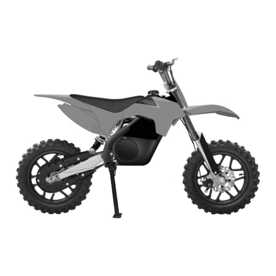
Electric Dirt Bike
OWNER'S MANUAL
Read and understand this entire manual before using!
NOTE: Manual illustrations are for demonstration purposes only.
Illustrations may not reflect exact appearance of actual product.
Specifications subject to change without notice.
OFF ROAD USE ONLY!!!
NEVER OPERATE THIS VEHICLE IF YOU ARE UNDER
AGE 12!!!
Advertisement
Table of Contents

Summary of Contents for Pitster Pro XJ-E
- Page 1 Electric Dirt Bike OWNER’S MANUAL Read and understand this entire manual before using! NOTE: Manual illustrations are for demonstration purposes only. Illustrations may not reflect exact appearance of actual product. Specifications subject to change without notice. OFF ROAD USE ONLY!!! NEVER OPERATE THIS VEHICLE IF YOU ARE UNDER AGE 12!!!
-
Page 2: Safety Warnings
INSTRODUCTION Thank you for purchasing this product. The proper care and maintenance that your vehicle requires is outlined in this manual. Following these instruction will ensure a long trouble-free operating life of this vehicle and your satisfaction with it. The owner’s manual corresponded to the latest state of this vehicle at the time of printing. Slight deviations resulting from continuing development and design can, however, not be completely excluded. - Page 3 Keep this product away from small children younger than age 12 and remember that this product is intended for use only by persons who are, at a minimum, completely comfortable and competent while operating the vehicle 145lbs ( 65kgs) Do not exceed total weight on this vehicle.
- Page 4 possible accidents. Do not ride the vehicle in mud, ice, puddles or water. Avoid excessive speed that can be associated with downhill rides. Never risk damaging surfaced such as a carpet or flooring by use of the vehicle in doors. Do not ride at night or when visibility is limited.
-
Page 5: Pin Location
Sticker A Sticker B PIN LOCATION PIN is stamp marked on an aluminum plate that is riveted on the steering column . PIN means the Product Identify Number which is unique for each unit. - Page 6 FUNCTION SWTICH OF 3 SPEED LIMIT ADJUSTABLE The 3-speed limit switch is located under the left side of motor cover. Below the switch, there are 3 letter standing for the different speed as follows, H: top speed around 25KMph. L: lowest speed around 8KMph. M: middle speed around 15KMph..
-
Page 7: Main Parts
MAIN PARTS Plastic fairing and seat (1-A) 11 Front brake disc 21 Driven sprocket Rubber grip L & R 12 Motor cover L & R 22 Chain Sleeve 13 Fork 23 Battery 2x12V 12AH Throttle 14 3-speed switch 24 Chain cover Front brake lever 15 Motor 25 Battery box... -
Page 8: Before You Begin
BEFORE YOU BEGIN Remove contents from box. Remove the foam separators that protect the components from damage during shipping. Inspect the contents of the box for scratches in the paint, dents or kinked cables that may occurr during shipping. Because the product was 85 percent assembled and packed at the factory, there should not be any problems, even if the box has a few scars or dents. - Page 9 mount the bolt (D) through the mudguard fixing bracket into the splintage (B) and tighten it. mount the bolt (C) bottom-up through the mudguard rear hole into the splintage (B) and tighten it. A:mudguard B:down splintage C:bolt M6X16 D: bolt M6 x16 ASSEMBLYNUMBER BOARD 1.
-
Page 10: Inflating The Tires
1. Uplift the frame to align the shock (A) mounting hole to the shackle joint hole. 2. Fix the bolt (B) through the shock mounting hole and shack joint and tighten the nut (C) securely with 10mm and 13mm open end wrench A:shock absorber B:bolt M8X40 C:nut M8... -
Page 11: Before Riding
The inflating should be done while the tire is cold. Tire maintenance Tire tread depth should be checked regularly.( Shallower tread means less grip of tire). You must stop to use the vehicle if the tire is pierced, disassemble the tire and check it carefully. Tire maintenance should be done by an authorized technician. -
Page 12: Safety Reminders
There are 2 charge port on this vehicle, one is located below the handlebar of battery box, and the other is fitted on the left side of motor cover ( see above picture). Warning: Failure to recharge the battery at least once a month may result in a battery that will no longer hold a charge. -
Page 13: Technical Specification Sheet
Tire Inflation Periodically inspect the tires for excess wear, and regularly check the tire pressure and re-inflate as necessary. If you get a flat tire, the inner tube can be patched or a new tube can be purchased from an authorized repair shop. ... -
Page 14: Repair And Maintenance
REPAIR AND MAINTENANCE Turn key switch “OFF” before conducting any maintenance procedures. Replacing The Fuse WARNING: To prevent shock, please follow above instructions accordingly and do not skip or combine any steps. - Page 15 Adjusting chain Checking the drive chain periodically to ensure longer chain life. Always keep it lubricated and tighten the chain as follows: Step 1 : Use the cross screwdriver to loose the 3pcs screws and remove the chain cover Step 2 : Loose the rear wheel axle nut with 17mm and 14mm open spanner, then loose the screw of caliper bracket, adjust the chain adjuster.
-
Page 16: Adjusting Brake
Adjusting brake Step 1: To adjust the brake tension, thread the brake lever adjuster in or out 1/4 or 1/2 turn until the required brake adjustments is attained. Most of brake adjustments are complete at this step, if the brake still need the further adjustment, Step 2: With 10mm open spanner, loose the brake cable and adjust the brake caliper arm to make the cable... -
Page 17: Battery Disposal
Avoid skidding to stop as this can cause you lose control or damage the rear tire. Testing the Brakes To use the brake, squeeze the lever to increase the pressure on the brake. The brake lever is fitted with a cable adjuster to compensate for cable stretch and/or to fine-tune the lever movement to brake engagement. -
Page 18: Troubleshooting Guide
TROUBLESHOOTING GUIDE Problem Possible cause Solution Charge the battery. A new battery should have been charged for at least 12 hours before using the vehicle for the first time and up to 8 hours after each subsequent use. Undercharged battery. Check all connectors. - Page 19 Driving conditions are too Use only on solid, flat clean and dry Surfaces such as stressful. pavement or level ground. The tires are inflated when shipped, but They invariably Tires are not properly will lose some pressure Between the point of Inflated.
-
Page 20: Circuit Diagram
CIRCUIT DIAGRAM... - Page 21 Please read the owner’s manual before riding. Never operate this vehicle if you are under age 12. Never use the vehicle on public road. OFF ROAD use only. Never ride with a passenger Always use an approved helmet and protective gear NEVER use with drugs or alcohol Cold tire pressure.
Need help?
Do you have a question about the XJ-E and is the answer not in the manual?
Questions and answers