
Related Manuals for Toro 09200


Summary of Contents for Toro 09200
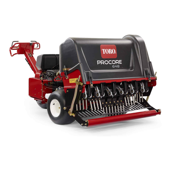
- Page 1 Form No. 3363-873 Rev A ProCore ® 648 Aerator Model No. 09200—Serial No. 290000801 and Up To register your product or download an Operator's Manual or Parts Catalog at no charge, go to www.Toro.com. Original Instructions (EN)
-
Page 2: Introduction
Whenever you need service, genuine Toro parts, or additional information, contact an Authorized Service Dealer or Toro Customer Service and have the model and serial numbers of your product ready. Figure 1 illustrates the location of the model and serial numbers on the product. -
Page 3: Table Of Contents
Contents Changing the Engine Oil and Filter ..... 36 Servicing the Spark Plugs........37 Fuel System Maintenance ........38 Introduction..............2 Replacing the Fuel Filter ........38 Safety ................4 Draining the Fuel Tank........38 Safe Operating Practices ........4 Electrical System Maintenance........ -
Page 4: Safety
Safety – Do not smoke. – Never refuel or drain the aerator indoors. Improper use or maintenance by the operator • Check that the operator presence controls, safety or owner can result in injury. To reduce the switches, and shields are attached and functioning potential for injury, comply with these safety properly. -
Page 5: Sound Power Level
• Use only Toro-approved attachments. The • Do not make sudden turns or rapid speed changes. warranty may be voided if the machine is used with • Reduce speed and use extreme caution on slopes. -
Page 6: Safety And Instructional Decals
Safety and Instructional Decals Safety decals and instructions are easily visible to the operator and are located near any area of potential danger. Replace any decal that is damaged or lost. 93–6696 1. Stored energy hazard—read the Operator’s Manual. 106-8835 1. - Page 7 110-4664 1. Read the Operator’s 3. Bolt size Manual. 2. Wrench size 4. Torque Battery Symbols Some or all of these symbols are on your battery 1. Explosion hazard 6. Keep bystanders a safe distance from the battery. 2. No fire, open flame, or 7.
- Page 8 106-8854 1. Read the Operator’s Manual. 4. Engine—start 7. To start the engine, turn the ignition key and unlock the parking brake; read the Operator’s Manual. 2. Engine—stop 8. To stop the engine, press the switch to 5. Read the Operator’s Manual; move the switch up to turn ground following on;...
- Page 9 115-4716 1. Warning—do not operate this machine unless you are trained. 7. Warning—stop the engine and read the instructions before servicing or performing maintenance. 2. Crushing hazard—Walk in a forward direction while operating 8. Entanglement hazard, belt; crushing hazard of hand or the machine, do not walk and face backwards when operating foot—stay away from moving parts, keep all guards and the machine, always look down and behind you when walking...
-
Page 10: Setup
Setup Loose Parts Use the chart below to verify that all parts have been shipped. Procedure Description Qty. Wheel assembly Install the rear wheels. Locknut (1/2 inch) Cable guide Install the handle. Bolt (5/16 x 1/2 inch) Bolt (1/4 x 1 inch) Activate and charge the battery. -
Page 11: Installing The Handle
Installing the Rear Wheels Parts needed for this procedure: Wheel assembly G00XXXX Figure 4 Procedure 1. Handle 3. Locknut 1. Remove the 8 lug nuts securing the rear of the 2. Fork 4. Cable guide aerator to the packaging. 2. Mount a wheel assembly onto each rear wheel hub 3. - Page 12 WARNING Charging the battery produces gasses that can explode. Never smoke near the battery and keep sparks and flames away from it. 7. When the battery is charged, disconnect the charger from the electrical outlet and battery posts. Note: After the battery has been activated, add only distilled water to replace normal loss, although maintenance-free batteries should not require water under normal operating conditions.
-
Page 13: Securing The Rear Hood (Ce Only)
WARNING Incorrect battery cable routing could damage the machine and cables causing sparks. Sparks can cause the battery gasses to explode, resulting in personal injury. • Always disconnect the negative (black) battery cable before disconnecting the positive (red) cable. • Always connect the positive (red) battery cable before connecting the negative (black) cable. -
Page 14: Securing The Belt Cover (Ce Only)
Securing the Belt Cover (CE Only) Parts needed for this procedure: Lanyard Pop rivet Bolt (1/4 x 1 inch) Locknut (1/4 inch) Figure 7 Procedure 1. Rear hood If you are setting up this machine for use in the European Union (CE), secure the belt cover as follows to comply with CE regulations. -
Page 15: Installing The Tine Holders, Turf Guards, And Tines
2. Using the hole in the belt cover, install the lanyard assembly with a pop rivet (Figure 10). Installing the Tine holders, Turf Guards, and Tines No Parts Required Procedure A wide selection of tine holders, turf guards, and tines are available for the aerator. -
Page 16: Product Overview
Parking Brake Product Overview To engage the parking brake, move the lever toward the engine. To disengage the parking brake, move the lever forward (Figure 13). Always set the parking brake when you stop the aerator or leave it unattended. Jog the traction lever forward and reverse to release the parking brake. - Page 17 Choke To start a cold engine, close the carburetor choke by moving choke control (Figure 14) fully forward. After the engine starts, regulate the choke to keep the engine running smoothly. As soon as possible, open the choke by pulling it backward. Manual Ground Follow Selector Switch Rotate the switch to the down position to turn off the TrueCore feature (Figure 14) Remove the bolt to access...
-
Page 18: Specifications
1590 lb (721 kg) Attachments/Accessories A selection of Toro approved attachments and accessories are available for use with the machine to enhance and expand its capabilities. Contact your Authorized Service Dealer or Distributor or go to www.Toro.com for a list of all approved attachments and accessories. -
Page 19: Operation
Operation DANGER In certain conditions during fueling, static Note: Determine the left and right sides of the electricity can be released causing a spark which machine from the normal operating position. can ignite the gasoline vapors. A fire or explosion from gasoline can burn you and others and can CAUTION damage property. -
Page 20: Checking The Engine Oil Level
Checking the Engine Oil Level Add the correct amount of gas stabilizer/conditioner to the gas. Service Interval: Before each use or daily (Check the Note: A fuel stabilizer/conditioner is most effective oil when the engine is cold.) when mixed with fresh gasoline. To minimize the The engine is shipped with oil in the crankcase;... -
Page 21: Checking The Hydraulic Fluid
Mobil. Contact Alternate fluids: If the Toro fluid is not available, other your local Toro Distributor for details. fluids may be used provided they meet all the following 1. -
Page 22: Cleaning The Engine Screen
Starting and Stopping the Engine Starting the Engine 1. Release the traction lever (bail) and set the parking brake. 2. Move the choke control to the On position before starting a cold engine. Note: A warm or hot engine may not require choking. -
Page 23: The Safety Interlock System
The Safety Interlock System CAUTION If safety interlock switches are disconnected or damaged the aerator could operate unexpectedly causing personal injury. • Do not tamper with the interlock switches. • Check the operation of the interlock switches daily and replace any damaged switches before operating the aerator. -
Page 24: Replacing Tines
5. Install tines into the #2 and #5 tine holders (Figure 26) Tighten the bolts. G010038 Figure 23 1. Tine arm 2. Tine holder 3. Loosely install the turf guards to the turf guard G010040 brackets with 4 turf guard clamps and 12 flange nuts Figure 26 (Figure 24). -
Page 25: Setting The Coring Depth
Setting the Coring Depth To set the coring depth of the aerator, proceed as follows: 1. Select the preferred tine for your application. 2. Lay the tine on the tine depth decal (Figure 28) with one end lined up with the desired depth of aeration (refer to the tine overlay on the decal). -
Page 26: Pushing/Pulling The Aerator By Hand
Pushing/Pulling the Aerator Resetting the System Control by Hand Circuit If the coring head is ever left in the aerating position Important: Never tow the aerator faster than 1 (run out of fuel, forget to install service latch for MPH because hydraulic component damage may storage, mechanical failure of engine/pump, etc.) the occur. - Page 27 carefully read all the safety instructions. Knowing WARNING this information could help you, your family, pets, or Driving on street or roadway without turn signals, bystanders avoid injury. lights, reflective markings, or a slow moving Important: Do not use the Hydroject trailer/tote vehicle emblem is dangerous and can lead to to trailer this aerator.
-
Page 28: Using The Line Marker
Using the Line Marker Use the line marker to align aeration rows (Figure 36). Figure 37 G010050 1. Weight transfer springs 2. Spring plate Figure 36 1. Line marker (storage 2. Line marker (alignment position) position) 2. Insert a 1/2 inch ratchet or breaker bar into the square hole in the spring plate (Figure 38). -
Page 29: Aerator Control Module (Acm)
lb (28.5 kg) to the machine. Up to two plates can be The ACM does not connect to an external computer or added. Refer to the Parts Catalog for these part numbers. hand held device, cannot be reprogrammed, and does not record intermittent fault troubleshooting data. -
Page 30: Operating Tips
Mini Tine (Quad Tine) If the ground is too firm to obtain the desired coring The mini-tine head developed by Toro is a very fast depth, the coring head can get into a bouncing rhythm. way to aerate due to the double row design. This coring This is due to the hard pan the tines are attempting head requires the hole spacing to be set at 2.5 inches... - Page 31 begin to lift the turf or damage to the root zone is and bearing damage due to excessive water pressure will excessive, proceed as follows: be avoided. A brush may be used to remove caked-on material. Use mild detergent to clean the covers. •...
-
Page 32: Maintenance
Maintenance Note: Determine the left and right sides of the machine from the normal operating position. Recommended Maintenance Schedule(s) Maintenance Service Maintenance Procedure Interval • Adjust the pump belt. • Change the hydraulic fluid and the return and charge filters. After the first 8 hours •... -
Page 33: Daily Maintenance Checklist
Daily Maintenance Checklist Duplicate this page for routine use. Maintenance Check Item For the week of: Mon. Tues. Wed. Thurs. Fri. Sat. Sun. Check the safety interlock operation. Check parking brake operation. Check the engine oil level. Check fuel level Check the air cleaner. -
Page 34: Jacking Instructions
Jacking Instructions 2. Place the jack securely under the frame plate just inside of the rear wheel (Figure 42). CAUTION When changing attachments, tires, or performing other service, use the correct blocks, hoists, and jacks. Make sure the machine is parked on a solid, level surface such as a concrete floor. -
Page 35: Lubrication
Lubrication Engine Maintenance Servicing the Air Cleaner Checking the Coring Head Bearings Service Interval: Every 25 hours—Clean the foam air filter element and check the paper Service Interval: Yearly—Check the coring head element for damage. bearings. Every 100 hours—Replace the paper air filter element. -
Page 36: Changing The Engine Oil And Filter
Changing the Engine Oil and 1. Wash the foam pre-filter in liquid soap and warm water. When clean, rinse it thoroughly. Filter 2. Dry the pre-filter by squeezing it in a clean cloth (do not wring). Service Interval: After the first 50 hours 3. -
Page 37: Servicing The Spark Plugs
14. Slowly add additional oil to bring the level to the F (full) mark on the dipstick. 15. Replace the fill cap. Servicing the Spark Plugs Service Interval: Every 200 hours—Check the spark plugs. Ensure that the air gap between the center and side electrodes is correct before installing each spark plug. -
Page 38: Fuel System Maintenance
Fuel System Maintenance Replacing the Fuel Filter Service Interval: Every 100 hours/Yearly (whichever comes first) Important: Never install a dirty filter if it is Figure 51 removed from the fuel line. 1. Center electrode insulator 3. Air gap (not to scale) 1. -
Page 39: Electrical System Maintenance
Electrical System 1. Park the machine on a level surface to ensure the fuel tank drains completely. Then, set the parking brake, Maintenance and turn the ignition key to off. Remove the key. 2. Close the fuel shut–off valve (Figure 52). Servicing the Battery 3. -
Page 40: Fuses
WARNING Incorrect battery cable routing could damage the machine and cables causing sparks. Sparks can cause the battery gasses to explode, resulting in personal injury. • Always disconnect the negative (black) battery cable before disconnecting the positive (red) cable. • Always connect the positive (red) battery cable before connecting the negative (black) cable. -
Page 41: Drive System Maintenance
Drive System Maintenance Checking the Tire Pressure Service Interval: Every 50 hours/Monthly (whichever comes first) Check to ensure that the air pressure in all tires is 12 psi (83 kPa). Check the tires when they are cold to get the most accurate pressure reading. -
Page 42: Belt Maintenance
Inspect the belts yearly for signs of wear, excessive cushion cracks, or large embedded debris. Replace them when needed. A complete belt service kit is available from your Authorized Toro Distributor. Figure 57 1. Pump shield 3. Loosen the pump belt idler bolt just enough to allow... -
Page 43: Controls System Maintenance
Controls System Hydraulic System Maintenance Maintenance WARNING Resetting the Ground Hydraulic fluid escaping under pressure can Following System penetrate skin and cause injury. Fluid injected into If the True Core ground following system requires the skin must be surgically removed within a few service of any kind (with the exception of turf guard hours by a doctor familiar with this form of injury replacement) or if the tine holders are contacting the... -
Page 44: Hydraulic System Test Ports
Do not overfill. Hydraulic System Test Ports The test ports are used to test the pressure in the hydraulic circuits. Contact your local Toro distributor for assistance. • Test Port G 2 (Figure 61) is used to assist in trouble... -
Page 45: Aerator Maintenance
Aerator Maintenance Replacing the Turf Guards All turf guards should be replaced if broken or worn to Checking the Fastener Torque less than 1/4 inch (6 mm) thickness. Broken turf guards can catch and tear turf creating undesirable damage. Service Interval: After the first 8 hours Check the coring head fasteners, tiller handle fasteners and wheel lug nuts to ensure proper torque is maintained. -
Page 46: Coring Head Timing
Coring Head Timing The coring head timing marks are easily identified by the G010069 marks in the casting. Figure 65 1. 21.2 inches (10 holes) 18.8 divided by 10 is 1.88, hole spacing is short by .12 inch from nominal (Figure 66). G010070 Figure 66 1. -
Page 47: Storage
11. Wash and dry entire unit. Remove tines, clean and C. Coat the cable terminals and battery posts with oil. Spray light oil mist on coring head bearings Grafo 112X skin-over grease (Toro Part No. (crank & damper links). 505-47) or petroleum jelly to prevent corrosion. -
Page 48: Troubleshooting
Troubleshooting Problem Possible Cause Corrective Action Starter does not crank 1. Traction lever not in neutral position. 1. Move traction lever to neutral position 2. The battery is dead. 2. Charge the battery. 3. Electrical connections are corroded or 3. Check electrical connections for good loose. - Page 49 Problem Possible Cause Corrective Action The head bounces while aerating. 1. The ground is too hard. 1. Refer to Operating Tips. 2. Relief setting/Restriction orifice. 2. Dynamic response of lift system. Adjust the system pressures. Refer to the Service Manual. 1.
-
Page 50: Schematics
Schematics G010075 Electrical Schematic (Rev. A) - Page 51 G010076 Hydraulic Schematic (Rev. A)
-
Page 52: Conditions And Products Covered
Countries Other than the United States or Canada Customers who have purchased Toro products exported from the United States or Canada should contact their Toro Distributor (Dealer) to obtain guarantee policies for your country, province, or state. If for any reason you are dissatisfied with your Distributor’s service or have difficulty obtaining guarantee information, contact the Toro importer.
Need help?
Do you have a question about the 09200 and is the answer not in the manual?
Questions and answers