Table of Contents
Advertisement
Quick Links
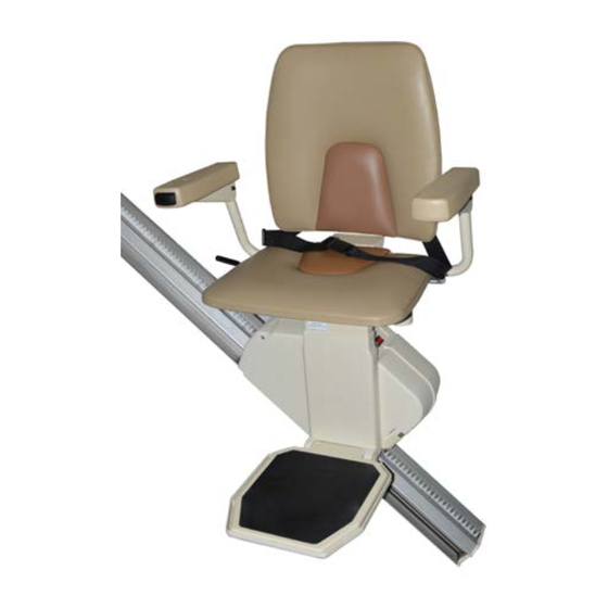
Stair Lift
SR601
INSTALLATION MANUAL
ATTENTION! STRICT ADHERENCE TO THESE INSTALLATION INSTRUCTIONS is required and will promote the safety of those installing this
product, as well as those who will ultimately use the lift for its intended purpose. Any deviation from these instructions will void the
LIMITED WARRANTY that accompanies the product. Additionally, any party installing the product who deviates from the INSTALLATION
INSTRUCTIONS shall be taken to agree to INDEMNIFY, SAVE AND HOLD HARMLESS the manufacturer from any and all loss, liability or
damage, including attorneys fees, that might arise out of or in connection with such deviation.
Part Number: 630-00065-01 Rev A
Advertisement
Table of Contents

Summary of Contents for Harman SR601
- Page 1 Stair Lift SR601 INSTALLATION MANUAL ATTENTION! STRICT ADHERENCE TO THESE INSTALLATION INSTRUCTIONS is required and will promote the safety of those installing this product, as well as those who will ultimately use the lift for its intended purpose. Any deviation from these instructions will void the LIMITED WARRANTY that accompanies the product.
-
Page 2: Table Of Contents
Pinnacle 101 Stair Lift CONTENTS Contents Read and understand this manual prior to attempting stair lift installations. Please refer to the Owner’s Manual for Limited PRELIMINARY CHECKS Warranty information and operating instructions. Tools Required ....... 3 The Owner’s Manual must be given to the owner of the lift before it is put into service. -
Page 3: Preliminary Checks
Nylon plugs (5) Power supply Seat swivel post with fasteners Manual overide tool Rail parts (plastic bag): Installation manual Extra plastic racks (2 or 3) Owner’s manual Top limit cam SR601 • Pinnacle 101 Stair Lift Installation TEC0081 20150915 P/N: 630-00065 revA... -
Page 4: Installation Procedures
Pinnacle 101 Stair Lift INSTALLATION PROCEDURES A. DETERMINE OVERALL RAIL LENGTH (Only if rail did not come pre-cut to length) 1: Determine any obstructions that will affect the position and length of the rail. These may include walls, doors, hallway orientation, etc. 2: Measure the overall length of the stairs from the nose at the top landing of the stairs to the floor at the bottom (nose to floor measurement, (128"). -
Page 5: Rail Installation
SR601 • Pinnacle 101 Stair Lift Installation TEC0081 20150915 P/N: 630-00065... - Page 6 Pinnacle 101 Stair Lift INSTALLATION PROCEDURES A. For double rails, the first rail bracket should be tightened in place so when turned over the back of the bracket touches the rear of the first step from the bottom landing. The second and third brackets should be placed and tightened on the steps on each side Figure 6-1...
-
Page 7: Chassis Installation
(2) bolts on the side of the chassis facing the wall. Do not ride on the chassis or lift until the install is complete. WARNING SR601 • Pinnacle 101 Stair Lift Installation TEC0081 20150915 P/N: 630-00065 revA... -
Page 8: Final Rail Installation
Pinnacle 101 Stair Lift INSTALLATION PROCEDURES D. FINAL RAIL INSTALLATION 1. Install the remaining plastic rack pieces in the upper rail. [Figure 8-1] 2. Use a hacksaw or chop saw to cut the last plastic Figure 8-1 rack piece flush with the rail end. Place something on the floor to catch debris or mark and cut the rack outside. - Page 9 7. Plug in the power supply at either end of the rail, depending on the closest or most convenient location of a wall power supply. Minimize wire length and intrusion. [Figure 9-3 & 9-4] Figure 9-4 SR601 • Pinnacle 101 Stair Lift Installation TEC0081 20150915 P/N: 630-00065 revA...
-
Page 10: Footrest And Seat Installation
Pinnacle 101 Stair Lift INSTALLATION PROCEDURES E. FOOTREST & SEAT INSTALLATION 1. Remove footrest from box and use the installation switch to drive the chassis downward to a position about 6" clear of the floor. This will provide a safe area to install and adjust the footrest. - Page 11 If any of the system controls or safety sensors are engaged the LED indicator light will turn to yellow. [Figure 11-6] Figure 11-6 SR601 • Pinnacle 101 Stair Lift Installation TEC0081 20150915 P/N: 630-00065 revA...
-
Page 12: Installation Procedures
Pinnacle 101 Stair Lift INSTALLATION PROCEDURES F. LED & AUDIBLE TONES 1. If the LED indicator light is not green, check the safety senors: Seat swivel sensor (seat should be in the • Figure 12-1 locked position) • Footrest lower sensor (check by pushing in 2. -
Page 13: Remote Control Operation
“ON/ OFF” switch to the “ON” position (I). 11. Test each remote control in both the up and down directions. SR601 • Pinnacle 101 Stair Lift Installation TEC0081 20150915 P/N: 630-00065 revA... -
Page 14: Completion Procedures
Pinnacle 101 Stair Lift COMPLETION PROCEDURES Completion Procedures 2. The final stopped position can be adjusted to accommodate the height of the user by repositioning the limit cam located in a slot in the rail. A. TEST ARMREST CONTROL SWITCH 3. -
Page 15: Additional System Checks
The beep will stop after 30 seconds, but the armrest LED indicator light will continue to flash orange. SR601 • Pinnacle 101 Stair Lift Installation TEC0081 20150915 P/N: 630-00065 revA... -
Page 16: Safety Systems Testing
Pinnacle 101 Stair Lift FOLDING RAIL INSTALLATION Folding Rail Option Installation Note - The photos in this section show a "left" folding rail, assembled to be installed on the left side of the stairway. If you’re assembling a "right’"side, please complete all of these steps in mirror-image to what’s shown. - Page 17 3" from the wall or more. This will leave about 1/2" of clearance at the ball of the gas-spring. [Figure 21-4] Figure 21-4 SR601 • Pinnacle 101 Stair Lift Installation TEC0081 20150915 P/N: 630-00065 revA...
- Page 18 Pinnacle 101 Stair Lift FOLDING RAIL INSTALLATION 7. Fasten down the near corner of the lower bracket using a drill that has extensions at least 10"long and a 3/8” socket. [Figure 22-1 & 22-2] 8. Measure from the side of the rail at the upper bracket of the folding rail.
- Page 19 5 & 6 (steps 7 & 8). 15. Test ride the unit a couple of times to verify that the folding rail is operating properly. SR601 • Pinnacle 101 Stair Lift Installation TEC0081 20150915 P/N: 630-00065 revA...
- Page 20 Stair Lift SR601 www.harmar.com | 800-833-0478 INSTALLATION MANUAL 2075 47th Street Sarasota, Florida 34234 TEC0003 20151008 P/N: 630-00005 revA...
Need help?
Do you have a question about the SR601 and is the answer not in the manual?
Questions and answers