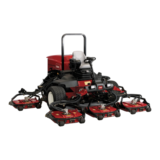
Toro 30868 Groundsmaster 4700-D Operator's Manual
Traction unit
Hide thumbs
Also See for 30868 Groundsmaster 4700-D:
- Service manual (298 pages) ,
- Installation instructions manual (20 pages) ,
- Operator's manual (92 pages)

Related Manuals for Toro 30868 Groundsmaster 4700-D


Summary of Contents for Toro 30868 Groundsmaster 4700-D
- Page 1 Form No. 3352-759 Groundsmaster® 4700-D Traction Unit Model No. 30868—Serial No. 250000001 and Up Register your product at www.Toro.com Original Instructions (EN)
-
Page 2: Table Of Contents
Tie Downs ........... 23 incorporated with the muffler assembly. Operating Characteristics ....... 23 Genuine Toro spark arresters are approved by the Standard Control Module (SCM) ..... 24 USDA Forestry Service. Operating Tips ........25 Maintenance ............ -
Page 3: Introduction
Whenever you need service, genuine Toro parts, or additional information, contact an Authorized Service 1. Safety alert symbol. Dealer or Toro Customer Service and have the model and serial numbers of your product ready. Figure 1 identifies the location of the model and serial numbers This manual uses two other words to highlight on the product. -
Page 4: Safety
Safety ◊ lack of awareness of the effect of ground conditions, especially slopes; • The owner/user can prevent and is responsible for This machine meets or exceeds CEN standard EN accidents or injuries occurring to himself or herself, 836:1997 (when appropriate decals applied), and ANSI other people, or property. -
Page 5: Maintenance And Storage
• Do not put hands or feet near or under rotating – before making height adjustment unless parts. Keep clear of the discharge opening at all adjustment can be made from the operator’s times. position. • Remember there is no such thing as a safe slope. –... -
Page 6: Toro Riding Mower Safety
The following list contains safety information specific • Do not touch the engine, silencer/muffler, or to Toro products or other safety information that you exhaust pipe while the engine is running or soon must know that is not included in the CEN, ISO, or after it has stopped because these areas could be ANSI standard. -
Page 7: Sound Pressure Level
• To ensure safety and accuracy, have an Authorized This unit does not exceed a vibration level of 0.5 m/s2 Toro Distributor check the maximum engine speed at the posterior based on measurements of identical with a tachometer. machines per ISO 2631 procedures. - Page 8 93-6680 93-7272 105-7506 1. Cutting/dismemberment hazard; fan—stay away fro moving 1. Read the Operator’s 4. Engine—preheat parts. Manual. 2. Engine—stop 5. Engine—start 3. On 105-3888 93-6699 1. Read the Operator’s Manual. 1. Machine speed 3. Continuous variable setting 2. To lock the parking brake, secure the brake pedals with the 2.
- Page 9 93-6686 1. Hydraulic oil 2. Read the Operator’s Manual. 105-9223 (Afx over part no. 105-38890 for CE) Battery Symbols 1. Warning-read the Operator’s Manual. 2. To start the engine (read the Operator’s Manual), sit in the Some or all of these symbols are on your battery operators’...
- Page 10 105-3889 107-1983 (Afx over part no. 105–3889 for CE) 1. Warning—read the Operator’s Manual. 2. Warning—lock the parking brake, stop the engine, and remove the ignition key before leaving the machine. 3. Thrown object hazard—keep bystanders a safe distance from the machine. 4.
- Page 11 108-4044 6. Fast 1. Lower the cutting unit(s). 11. Power Take-off (PTO) 2. Raise the cutting unit(s). 7. Continuous variable setting 12. High 3. Right cutting unit (GM 4700-D only) 8. Slow 13. Low 4. Center cutting units 9. Engage 14.
- Page 12 105-9895...
-
Page 13: Setup
Setup Loose Parts Use the chart below to verify that all parts have been shipped. Step Description Qty. Seat Kit, Model 30398 (sold separately) Seat Suspension Kit, Model 30395 (sold separately) Seat belt Install the seat, seat belt, and manual Capscrew, 7/16-20 x 1 inch tube. -
Page 14: Greasing The Machine
Step Step Greasing the Machine Reading the Manuals and Viewing the Video No Parts Required Parts needed for this step: Procedure Operator’s Manual Before the machine is operated, it must be greased Engine Operator’s Manual to ensure proper lubrication. Refer to Lubrication, Parts Catalog page 32. -
Page 15: Product Overview
Product Overview Figure 3 1. Steering wheel 4. Traction pedal 7. ROPS (Rollover Protection System) 2. Brakes 5. Manual tube 3. Cutting unit 6. Hood/engine compartment Controls Engine Oil Pressure Warning Light The light (Figure 4 ) illuminates when the engine oil Traction Pedal pressure is dangerously low. -
Page 16: Brake Pedals
Figure 5 1. Forward speed limiter 2. Reverse speed limiter screw screw Brake Pedals Two foot pedals (Figure 6 ) operate individual wheel brakes for turning assistance, parking, and to aid in obtaining better side hill traction. A latch connects the pedals for parking brake operation and transport. -
Page 17: Lift Lever
Figure 8 1. Fuel gauge Cutting Unit Lift Latch (CE) Figure 7 1. Throttle control 5. PTO switch The cutting unit lift latch (Figure 9 ) locks the center 2. Lift lever 6. Hi-Lo speed control 3. Hour meter 7. Power point five cutting unit lift levers when the cutting units are in 4. - Page 18 A selection of Toro approved attachments and accessories are available for use with the machine to enhance and expand its capabilities. Contact your Authorized Service Dealer or Distributor or go to www.Toro.com for a list of all approved attachments and accessories.
-
Page 19: Specifications
Check level of coolant at the beginning of each day. temperatures) Capacity of system is 2-3/4 gal. (10.4 l). Note: Toro Premium Engine oil is available 1. Carefully remove the radiator cap and expansion from your distributor in either 15W-40 or 10W-30 tank cap (Figure 12 ). -
Page 20: Filling The Fuel Tank
If the engine has been running, the pressurized, hot coolant can escape and cause burns. • Do not open the radiator cap when the engine is running. • Use a rag when opening the radiator cap, and open the cap slowly to allow steam to escape. -
Page 21: Checking The Tire Pressure
(Available in 5 gallon pails or 55 gallon drums. See parts catalog or Toro distributor for part numbers.) Alternate fluids: If the Toro fluid is not available, other fluids may be used provided they meet all the following material properties and industry specifications. We do not recommend the use of synthetic fluid. -
Page 22: Checking The Interlock Switches
Checking the Interlock 2. Move the throttle control to the low idle position. Switches 3. Turn the ignition key to the Run position. The glow indicator will light. 4. When the glow indicator dims, turn the ignition key to the Start position. Release the key immediately If safety interlock switches are disconnected when the engine starts and allow it to return to or damaged the machine could operate... -
Page 23: Jacking Points
Operating Characteristics hydraulic pump and pushing or towing the machine. Do not push or tow the machine for more than 1/4 Practice driving the machine because it has a hydrostatic mile (0.4 km). transmission and its characteristics are different than Important: Do not push or tow the machine many turf maintenance machines. -
Page 24: Standard Control Module (Scm)
This allows the turbo charger to cool down before The start circuit input is energized by 12 VDC. All shutting the engine off. Failure to do so may lead other inputs are energized when the circuit is closed to turbo-charger trouble. to ground. -
Page 25: Operating Tips
Each row (across) in the logic chart below identifies the left column. Symbols identify specific circuit input and output requirements for each specific condition including: energized to voltage, closed to product function. Product functions are listed in ground, and open to ground. Note: - Indicates a circuit closed to ground. - Page 26 • Requires more horsepower to run. • Tends to discharge further left and can tend to windrow at lower heights of cut. Do not use the high lift blade with the mulching baffle. The blade could break, resulting in personal injury or death. Always Mow with Sharp Blades A sharp blade cuts cleanly and without tearing or shredding the grass blades like a dull blade.
- Page 27 Cutting Unit Pitch We recommend a blade pitch of 5/16 in. (7.9 mm). A pitch larger than 5/16 in. (7.9 mm) will result in less power required, larger clippings, and a poorer quality of cut. A pitch less than 5/16 in. (7.9 mm) will result in more power required, smaller clippings and a better quality of cut.
-
Page 28: Maintenance
Maintenance Note: Determine the left and right sides of the machine from the normal operating position. Recommended Maintenance Schedule(s) Maintenance Maintenance Procedure Service Interval • Torque the wheel nuts. After the rst use After the rst 50 • Change the engine oil and lter. operating hours •... - Page 29 Maintenance Maintenance Procedure Service Interval • Drain and clean the fuel tank. • Check the tire pressure. • Check all fasteners. Before storage • Grease or oil all grease ttings and pivot points. • Paint chipped surfaces. • Check the fuel lines and connections. •...
-
Page 30: Daily Maintenance Checklist
Daily Maintenance Checklist Duplicate this page for routine use. For the week of: Maintenance Check Item Mon. Tues. Sat. Sun. Wed. Thurs. Fri. Check the safety interlock operation. Check the brake operation. Check the engine oil and fuel level. Check the cooling system uid level. -
Page 31: Service Interval Chart
Service Interval Chart Figure 18 If you leave the key in the ignition switch, someone could accidently start the engine and seriously injure you or other bystanders. Remove the key from the ignition before you do any maintenance. -
Page 32: Premaintenance Procedures
Premaintenance Lubrication Procedures Greasing the Bearings and Bushings Removing the Hood The machine has grease fittings that must be lubricated To gain additional access to engine compartment, the regularly with No. 2 General Purpose Lithium Base hood may be removed from traction unit. Grease. -
Page 33: Engine Maintenance
Rear roller bearings (2 per cutting unit) (Figure 26 ) Note: The flush fittings on the rollers (Figure 26 ) Figure 23 require a grease gun nozzle adapter. Order Toro 1. Top tting on king pin Part No. 107-1998 from your Authorized Toro Distributor. -
Page 34: Servicing The Engine Oil And Filter
Figure 27 1. Air cleaner indicator Important: Be sure the cover is seated correctly Figure 29 and seals with the air cleaner body. 1. Air cleaner primary lter 1. Pull the latch outward and rotate the air cleaner cover counterclockwise (Figure 28 ). Important: Never attempt to clean the safety filter (Figure 30 ). -
Page 35: Adjusting The Throttle
1. Remove the rear drain plug (Figure 31 ) and let the oil flow into a drain pan. When the oil stops, install the drain plug. Figure 33 Figure 31 1. Throttle cable 1. Engine oil drain plug 2. Remove the oil filter (Figure 32 ). Apply a light coat Fuel System of clean oil to the new filter seal before screwing it on. -
Page 36: Fuel Lines And Connections
Fuel Lines and Connections Check the fuel lines and connections every 400 hours or yearly, whichever comes first. Inspect them for deterioration, damage, or loose connections. Water Separator Drain water or other contaminants from the water separator (Figure 34 ) daily. Figure 35 1. -
Page 37: Bleeding Air From The Injectors
3. Open the air bleed screw on the fuel injection 3. Turn the key in the ignition switch to the Start pump (Figure 36 ). position and watch the fuel flow around the connector. Turn the key to the Off position when solid flow is observed. -
Page 38: Battery Care
Rinse with clear water. Coat the battery posts and cable connectors with Grafo 112X Battery posts, terminals, and related (skin-over) grease (Toro Part No. 505-47) or petroleum accessories contain lead and lead jelly to prevent corrosion. -
Page 39: Drive System Maintenance
Figure 40 Drive System Maintenance Figure 41 1. Check/drain plug Checking the Torque of the 2. Remove the plug on the planetary (Figure 41 ). Oil Wheel Nuts should be at the bottom of the check plug hole. 3. Add gear oil to the hole in the planetary, if necessary, to bring the oil up to the proper level. -
Page 40: Checking The Rear Axle Lubricant
2. Place a drain pan under the hub, remove the plug, and allow the oil to drain. 3. Place another drain pan under the brake housing on the other side of the wheel (Figure 43 ). Figure 44 1. Check plug 2. -
Page 41: Checking The Rear Wheel Toe-In
cutting units to the floor. Depress only the right brake pedal and engage the parking brake. 2. Jack up left side of machine until left front tire is off the shop floor. Support machine with jack stands to prevent it from falling accidentally. 3. -
Page 42: Brake Maintenance
Figure 48 Figure 50 1. Rear screen latch 1. Oil cooler 2. Radiator Important: Cleaning the radiator or oil 2. Rotate latches (Figure 49 ) securing the oil cooler to the frame. cooler with water will promote premature corrosion damage to components and compact debris. -
Page 43: Belt Maintenance
Change the 2 hydraulic filters initially after the first 200 operating hours. Thereafter, change the filters after every 800 operating hours, in normal conditions. Use Toro replacement filters Part No. 94-2621 for the rear (cutting unit) of the machine and 75-1310 for the front (charge) of the machine. -
Page 44: Checking The Hydraulic Lines And Hoses
Hydraulic System Test Ports The test ports are used to test the pressure in the hydraulic circuits. Contact your local Toro distributor for assistance. Test Port A (Figure 55 ), located on rear of filter manifold, under right hand frame rail. Used to measure the traction system charge pressure. -
Page 45: Adjusting The Counterbalance
Figure 58 1. Test port F (Decks) 2. Test port G (Decks) Figure 56 Test Port H (Figure 59 ) located on rear traction circuit 1. Test port B (Counter 2. Test port C ( Four wheel hard line. Used to measure reverse traction pressure. balance) drive) Test Port I (Figure 59 ) located on front traction circuit... -
Page 46: Cleaning
Figure 60 1. Counterbalance dial 2. Traction assist valve The traction assist valve (Figure 60 ) is used to boost the pressure in the counterbalance circuit. Recommended traction assist counterbalance pressure is 700 psi when traction pressure is above 1800 psi. Rotate the screw (Figure 60 ) clockwise to increase the pressure or counterclockwise to decrease the pressure. -
Page 47: Storage
B. Clean the battery, terminals, and posts with a wire brush and baking soda solution. C. Coat the cable terminals and battery posts with Grafo 112X skin-over grease (Toro Part No. 505-47) or petroleum jelly to prevent corrosion. D. Slowly recharge the battery every 60 days for 24 hours to prevent lead sulfation of the battery. -
Page 48: Schematics
Schematics Electrical Schematic (Rev. B) - Page 49 Hydraulic Schematic (Rev. D)
- Page 50 Notes:...
- Page 51 Notes:...
- Page 52 (Dealer) to obtain guarantee policies for your country, province, or state. If for any reason you are dissatised with your Distributor’s service or have difculty obtaining guarantee information, contact the Toro importer. If all other remedies fail, you may contact us at Toro Warranty Company.
Need help?
Do you have a question about the 30868 Groundsmaster 4700-D and is the answer not in the manual?
Questions and answers