Advertisement
Table of Contents
TH146 User Console
1. Introduction
1.1
Applications
The TH146-N-DE electronic controller can be used to control a heat
pump system. The following devices can be connected to the con-
troller:
heat pump
auxiliary heating (furnace)
air recirculation fan
humidifier
dual-register meter (dual energy)
remote control device (for the unoccupied mode)
1.2
Supplied Parts
• CT280-HP-2H1C control module
• TH146 console with two wall anchors and mounting screws
• AC144-03 outdoor temperature sensor (3 m or 10 ft) with
mounting clip (see section 2.7)
1.3
Accessories
• RC845 relay (see section 2.5)
• AC146-410 plenum temperature sensor (see section 2.8)
• CT241 telephone controller (see section 2.10)
TH146-N-DE
CT280-HP-2H1C Control Module
2. Installation
2.1
Control Module (CT280-HP-2H1C)
Install the control module on the furnace's electrical panel, away
from the heat source.
2.2
User Console (TH146)
Install the console in the area where you wish to measure the tem-
perature and humidity. Avoid locations where there are air drafts
(e.g., top of staircase or air outlet) or stagnant air (behind a door).
Do not install the console on a wall hiding air ducts nor expose it to
direct sunlight.
NOTE: If this controller replaces an existing thermostat, the wires
that were connected to the thermostat can be used to connect the
console. The maximum wire length is 30 m (100 feet).
1)
Choose a location about 5 ft. (1.5 m) above the floor on an
inside wall.
2)
Loosen the captive screw under the console.
3)
Detach the console from its base by pulling the bottom section.
4)
Secure the base using the wall anchors and screws.
5)
Connect the console to controller terminals TH and TH (no
polarity).
2.3
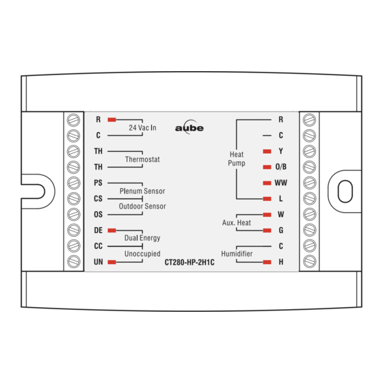
Heat Pump
Connect the heat pump to the controller as follows:
• Controller terminals R and C to heat pump terminals R and C
(see section 2.4)
• Controller terminal Y to heat pump terminal Y
• Controller terminal O/B to heat pump terminal O
• Controller terminal WW to heat pump terminal WW
TH146-N-DE
Installation Guide
AC144-03 Outdoor
Temperature Sensor
400-280-000-G
9/22/06
1/8
Advertisement
Table of Contents

Summary of Contents for Aube Technologies Non-programmable Heat Pump Controller TH146-N-DE
- Page 1 TH146 User Console 1. Introduction Applications The TH146-N-DE electronic controller can be used to control a heat pump system. The following devices can be connected to the con- troller: heat pump auxiliary heating (furnace) air recirculation fan humidifier dual-register meter (dual energy) remote control device (for the unoccupied mode) Supplied Parts •...
- Page 2 • Controller terminal L to heat pump terminal L • Controller terminal W to heat pump terminal W (see section 2.5) • Controller terminal G to heat pump terminal G (see section 2.5) 24 V Transformer You might need a 24 V transformer if you have an add-on installa- tion.
- Page 3 3.1.1 Backlight (SW1) BL ON: The screen is always backlit. AUTO: The screen is backlit only when a button is pressed. The backlight remains on for 12 seconds. 3.1.2 Access Mode (SW2) INST: Installer mode. Gives access to all configuration parameters. NOTE: In this mode, the short-cycle protection is disabled and the interstage delay is reduced to 1 minute.
- Page 4 Configuration Menu Item Parameters Display Temperature scale Balance point low Balance point high Defrost point Installation type Cycles per hour “Smart fan” Interstage delay Outdoor temperature display Humidifier operating mode Automatic humidity adjustment Humidity setpoint Humidity offset NOTE: Only the humidity setpoint or humidity offset (item 12) is available when the controller is placed in user mode (SW2 switch). TH146-N-DE Options Default...
- Page 5 Connection Diagram — New Installation TH146 16 - 22 AWG 16 - 22 AWG Dual Energy AC144-03 16 - 22 AWG TH146-N-DE AC146-410 16 - 22 AWG CT280-HP-2H1C CT241 16 - 22 AWG Heat Pump 16 - 18 AWG Compressor Valve Defrost Fault...
- Page 6 Connection Diagram — Add-on Installation Heat Pump 24 V Transformer TH146 AC146-410 16 - 18 AWG 16 - 22 AWG Compressor Valve Defrost CT280-HP-2H1C Fault 16 - 18 AWG 16 - 22 AWG 16 - 22 AWG 16 - 22 AWG 16 - 18 AWG Dual Energy 16 - 18 AWG...
- Page 7 Emergency heat mode System fault System operating mode selection Temperature adjustment 5. Operation System Operating Mode (Heating/Cooling) Press MODE to place the controller in one of the following modes. HEAT The system is in heating mode. COOL The system is in cooling mode. The system is in automatic changeover.
-
Page 8: Technical Specifications
Humidity level set by user Set the humidity level or offset using the • humidity level: 5% to 60% • offset: -9% to 9% Press the button to exit. symbol is displayed when the humidifier is On. Unoccupied Mode The controller can be placed in unoccupied mode via a remote con- trol device such as Aube’s CT241 telephone controller (see section 2.10).
Need help?
Do you have a question about the Non-programmable Heat Pump Controller TH146-N-DE and is the answer not in the manual?
Questions and answers