Table of Contents
Advertisement
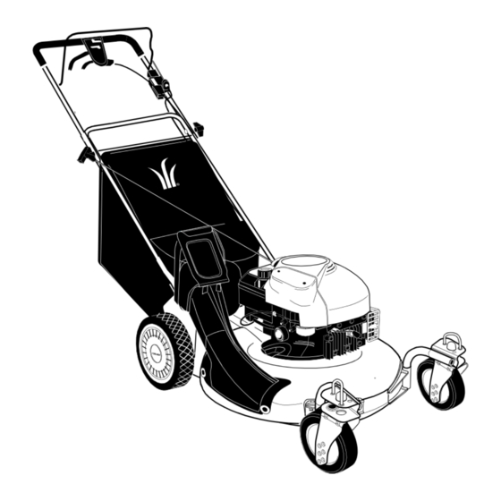
OPERATOR'S MANUAL
Model Number
SC 621
SC 621E
Model SC 621 Shown
IMPORTANT: READ SAFETY RULES AND INSTRUCTIONS CAREFULLY
Warning:
This unit is equipped with an internal combustion engine and should not be used on or near any unimproved forest-
covered, brush-covered or grass-covered land unless the engine's exhaust system is equipped with a spark arrester meeting
applicable local or state laws (if any). If a spark arrester is used, it should be maintained in effective working order by the operator.
In the State of California the above is required by law (Section 4442 of the California Public Resources Code). Other states may have
similar laws. Federal laws apply on federal lands. A spark arrester for the muffler is available through your nearest engine authorized
service dealer or contact the service department, P.O. Box 368023 Cleveland, Ohio 44136-9722.
CUB CADET CORP. P.O. BOX 368023 CLEVELAND, OHIO 44136-9722
FORM NO. 770-10090A.fm
PRINTED IN U.S.A.
(12/99)
Advertisement
Table of Contents

Subscribe to Our Youtube Channel
Related Manuals for Cub Cadet SC 621


Summary of Contents for Cub Cadet SC 621
-
Page 1: Model Number
Federal laws apply on federal lands. A spark arrester for the muffler is available through your nearest engine authorized service dealer or contact the service department, P.O. Box 368023 Cleveland, Ohio 44136-9722. CUB CADET CORP. P.O. BOX 368023 CLEVELAND, OHIO 44136-9722 FORM NO. 770-10090A.fm PRINTED IN U.S.A. -
Page 2: Table Of Contents
(Model Number) (Serial Number) Copy the model number here: Copy the serial number here: CUB CADET CORP. P.O. BOX 368023 CLEVELAND, OHIO 44136 CALLING CUSTOMER SUPPORT If you have difficulty assembling this product or have any questions regarding the controls, operation or maintenance of this unit, please call the Customer Dealer Referral Line. -
Page 3: Maintaining Safety
SECTION 1: MAINTAINING SAFETY This Warning symbol points out important safety instructions which, if not followed, could endanger the personal safety and/or property of yourself and others. Read and follow all instructions in this manual before attempting to operate your lawn mower. Failure to comply with these instructions may result in personal injury. -
Page 4: Slope Operation
CHILDREN • Never operate the mower in wet grass. Always be sure of your footing. A slip and fall can cause serious Tragic accidents can occur if the operator is not alert to the personal injury. Keep a firm hold on the handle and presence of children. - Page 5 • After striking a foreign object, stop the engine, protection, frequently check components and replace remove the wire from the spark plug, and thoroughly with manufacturer’s recommended parts, when inspect the mower for any damage. Repair the necessary. damage before starting and operating the mower. •...
-
Page 6: Slope Gauge
SECTION 2: SLOPE GAUGE Use this page as a guide to determine slopes where you may not operate safely. Do not operate your lawn mower on such slopes. -
Page 7: Assembling Your Lawn Mower
SECTION 3: ASSEMBLING YOUR LAWN MOWER This unit is shipped without gasoline or oil • Remove grass bag from unit and set it aside. IMPORTANT: in the engine. Be certain to service engine with gasoline • Lift up and pull back on the upper handle to raise and oil as instructed in the separate engine manual the handle into the operating position. -
Page 8: Know Your Lawn Mower
• The rope guide, which is connected to the support Lower rod, is located on the right side of lower handle. Handle See Figure 5. Starter • With the spark plug wire disconnected and Rope grounded, hold the blade control handle against the upper handle, and pull the starter rope out of the Support engine. -
Page 9: Operating Your Lawn Mower
Stopping Engine Front Wheel Caster Locks The caster locks are located on top of each caster • Release blade control handle to stop the engine wheel. Refer to the Adjustment Section. and the blade. Engine Controls • Disconnect spark plug wire and ground it to the See the separate engine manual for the location and post on the engine. -
Page 10: Starting Engine
• Squeeze the drive clutch control and pull the WARNING: Do not remove the battery mower backward. Do the rear wheels lock? pack from the handle panel for any reason • Is the drive clutch control cable free of kinks or other than replacement. -
Page 11: Emptying The Grass Bag
Emptying the Grass Bag be adjusted to the condition of the lawn. If mowing has been delayed and the grass has been allowed to grow • While holding the grass bag by both the rear handle in excess of 4”, mulching is not recommended. Mow and the lower handle, lift the grass bag straight up using the grass bag to reduce the grass height to 3 1/4”... -
Page 12: Making Adjustments
SECTION 6: MAKING ADJUSTMENTS Handle Height Adjustment WARNING: Do not at any time make any adjustments without first stopping engine Your mower is shipped with the handle in the higher and disconnecting spark plug wire. height position. To lower the height proceed as follows: •... -
Page 13: Maintaining Your Lawn Mower
Bottom View Bottom View Speed Control Upper Adjustment Lever Upper Handle Wheel Handle Drive Clutch Control Adjustable Cable Figure 14 Bracket Shift Lever Cable Adjustment Hex Nut Periodic adjustment of the six speed shift cable may be required due to normal wear on the cable. Adjustment is needed if all six speeds do not work. -
Page 14: General Recommendations
General Recommendations Maintenance • Always observe safety rules when performing any NOTE: When tipping the unit, empty the fuel tank and maintenance. keep the spark plug side of engine up. Never tip the • The warranty on this lawn mower does not cover mower more than 90 degrees and do not leave the items that have been subjected to operator abuse mower tipped for any length of time. - Page 15 • Remove the center bolt which secures the blade to the crankshaft followed by blade bell support, blade, and blade adapter. Blade Adapter • Move the cutting height adjustment to the highest position. • Remove the three hex screws holding the baffle to Blade Bell the deck and pivot baffle towards the rear of the Support...
- Page 16 • Place the belt between the two pulley halves on the Transmission crankshaft. Make sure to route the belt inside the Pulley belt guard pin. See Figure 21. Belt Upper Pulley Belt Keeper Half Bracket Idler Pulley Transmission Bracket Belt Idler Pulley Lower Bolt and...
-
Page 17: Storing Your Lawn Mower
• Pivot the baffle back to its original position and • Tighten the hex bolt to secure the blade to torque: secure with three hex screws earlier removed. 450-600 in. lbs. • Lightly lubricate the inside of the blade adapter and reinstall the spacer, wave washer, blade adapter assembly, and blade in the correct order. - Page 18 Models SC 621 and SC 621E Transmission Assembly for Reference only Pulley Assembly for Reference only 56 16 25...
- Page 19 Models SC 621 and SC 621E Ref. Ref. Part No. Description Part No. Description 710-0134 Carriage Screw 1/4-20 x .62 682-9024 Caster Bracket Assembly: RH 710-0654A Screw TT:3/8-18:1.00 682-9026 Caster Bracket Assembly: LH 710-0703 Carriage Screw 1/4-20 x .750 711-1146 Caster Axle .374 Dia x 2.50”...
- Page 20 Model SC 621E 42 41...
- Page 21 Model SC 621E Ref. Ref. Part No. Description Part No. Description 710-1174 Carriage Bolt 5/16-18 x 2.0 631-0071 Grass Bag Cover 714-0104 Cotter Pin .072 x 1.12 Lg. 747-0939 Pivot Rod 720-0241 Knob Assembly 5/16-18 726-0106 Cap Nut 726-0240 Strap 4.3” Lg. 747-0937 Frame (Grassbag) 736-0451...
- Page 22 Model SC 621...
- Page 23 Model SC 621 Ref. Ref. Part No. Part Description Part No. Part Description 710-1174 Carriage Bolt 5/16-18 x 2.0 731-0905A Lower Control Housing 714-0104 Cotter Pin .072 x 1.12 Lg. 731-0906 Cable Mounting Cap 720-0241 Knob Ass’y Wing Nut 5/16-18...
- Page 24 Models SC 621 and SC 621E Ref. Part No. Part Description 746-0939 6 Speed Cable 656-0613 Pulley Ass’y Multi-Speed 710-0167 Carriage Screw 1/4-20 x .50 710-1652 Hex Washer Screw 1/4-14 x .625 711-1114 Pivot Shaft 712-0287 Nut 1/4-20 732-0807 Torsion Spring LH 736-0270 Bell Washer .265 x .75 x .062...
- Page 25 Models SC 621 and SC 621E Ref. Part No. Part Description Transmission Assembly 618-0263A 712-3025 Hex Jam Nut 5/16-24 736-0425 Bell Washer .325 x .930 756-0656 Pulley 736-3084 Flat Washer .510 x 1.120 712-0896 Hex Jam Nut 1/4-28 782-7598 Belt Keeper...
- Page 26 NOTES...
-
Page 28: Cleveland, Ohio
How to obtain service Contact your authorized Cub Cadet servicing dealer who sold you your Cub Cadet equipment. If this dealer is not available, see the Consumer Yellow Pages under “lawn mowers” for the name of a dealer near you.
Need help?
Do you have a question about the SC 621 and is the answer not in the manual?
Questions and answers