Table of Contents
Advertisement
Advertisement
Table of Contents

Related Manuals for WatchNet MPIX-21BIMR

Summary of Contents for WatchNet MPIX-21BIMR
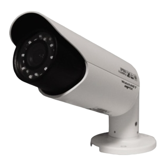
- Page 1 MPIX BIMR Network Camera (With Integrated Bracket) User’s Manual...
- Page 2 Welcome Thank you for purchasing our network camera! This user’s manual is designed to be a reference tool for your system. Please read the following safeguard and warnings carefully before you use this series product! Please keep this user’s manual well for future reference!
-
Page 3: Important Safeguards And Warnings
Important Safeguards and Warnings 1.Electrical safety All installation and operation here should conform to your local electrical safety codes. The power shall conform to the requirement in the SELV (Safety Extra Low Voltage) and the Limited power source is rated 12V DC or 24V AC in the IEC60950-1. (Refer to general introduction) Please note: Do not connect two power supplying sources to the device at the same time;... - Page 4 Do not touch the CCD (CMOS) optic component. You can use the blower to clean the dust on the lens surface. Always use the dry soft cloth to clean the device. If there is too much dust, please use the water to dilute the mild detergent first and then use it to clean the device.
-
Page 5: Table Of Contents
Table of Contents General Introduction ...................... 1 Overview ......................1 Features ......................1 Specifications ....................2 1.3.1 Performance ....................2 1.3.2 Factory Default Setup ................. 3 Structure ........................11 Multiple-function Combination Cable............... 11 Framework and Dimension ................12 Bidirectional talk ....................13 2.3.1 Device-end to PC-end................ - Page 6 Operation ......................21 Web Operation ......................24 Network Connection ..................24 Login and Main Interface ................. 24 FAQ ..........................27 Appendix Toxic or Hazardous Materials or Elements ..........28...
-
Page 7: General Introduction
1 General Introduction 1.1 Overview This series network camera integrates the traditional camera and network video technology. It adopts audio and video data collection, transmission together. It can connect to the network directly without any auxiliary device. This series network camera product uses standard H.264 video compression technology and G.711a audio compression technology, which maximally guarantee the audio and video quality. -
Page 8: Specifications
The enclosure conforms to the IP 66 protection. Has the waterproof function. 1.3 Specifications 1.3.1 Performance Please refer to the following sheet for network camera performance specification. Model MPIX-21BIMR Parameter Main Processor TI Davinci high performance DSP Embedded LINUX System... -
Page 9: Factory Default Setup
1250g(Excluding box) Installation Bracket is included in the accessories bag. IR Distance 20~30m Protection Level IP66 1.3.2 Factory Default Setup Please refer to the following sheet for factory default setup information. Default Setup Setup Item MPIX-21BIMR Config File Normal Brightness... - Page 10 Default Setup Setup Item MPIX-21BIMR Contrast Saturation Sharpness Anti-flicker Outdoor Exposure Mode Auto Scene Mode Auto Day/night Mode Auto Mirror Flip Profile Management Normal Bit stream General type Encode H.264 mode Resolution 1080P(1920*1080) 1.3M(1280*960) PAL:25 Frame Rate(FPS) NTSC:30 Bit Rate...
- Page 11 Default Setup Setup Item MPIX-21BIMR Snapshot General Type Image Size 1080P(1920*1080) Snapshot Quality Better Bit Rate Main stream Interval Privacy Disable Mask Video Overlay Channel Enable Title Time Title Enable Snapshot C:\PictureDownload Path Path Record Path C:\RecordDownload Enable Enable Main Stream Encode G.711A...
- Page 12 Default Setup Setup Item MPIX-21BIMR HTTP Port RTSP Port HTTPs On Disable HTTPs Port Enable Disable PPPoE Username none Password Server Type Disable,DVRID.com Server dvrid.com Address Domain none Name DDNS Username none Password **** Update 10 minutes Period Trusted IP Filter...
- Page 13 Default Setup Setup Item MPIX-21BIMR Read public Community Write private Community Trap Address Trap Port SNMP v1 Disable SNMP v2 Disable SNMP v3 Disable Enable Enable Bonjour Server “SN”. It depends on the device. Name Enable Enable Main Multicast 239.255.42.42...
- Page 14 Default Setup Setup Item MPIX-21BIMR Record 10 seconds Delay Relay out Enable Record 10 seconds Delay Send Email Disable Snapshot Disable Enable Disable Relay in Alarm 1 Anti-dither 0 seconds Sensor Type Record Alarm Enable Channel Activation Record 10 seconds...
- Page 15 Default Setup Setup Item MPIX-21BIMR Delay Enable Disable Record Enable Record 10 seconds IP Conflict Delay Relay out Enable Relay 10 seconds Delay Disable Record Holiday Schedule Disable Snapshot Enable FTP Disable Server Address Port Username anonymity Password Remote share...
- Page 16 Default Setup Setup Item MPIX-21BIMR NTP Server clock.isc.org Port Update 10 minutes Period Anonymous Account Disable Login Auto Reboot Enable, Tuesday 02:00 Auto Maintenance Auto Delete Disable Old Files...
-
Page 17: Structure
2 Structure 2.1 Multiple-function Combination Cable You can refer to the following figure for multiple-function combination cable information. See Figure Figure 2-1 Multiple-function combination cable Please refer to the following sheet for detailed information. Port Name Function Connection Note DC 12V/AC Power input Power port. -
Page 18: Framework And Dimension
Port Name Name Note ALARM_COM Alarm output public port. Alarm output port. It is to output the alarm signal to the alarm device. ALARM_NO NO: normal open alarm output port. It works with the ALARM_COM port. I/O Port Alarm input port 1. It is to receive the on-off signal ALARM_IN1 from the external alarm source. -
Page 19: Bidirectional Talk
Figure 2-3 Dimension illustration 2 Figure 2-4 Dimension illustration 3 2.3 Bidirectional talk 2.3.1 Device-end to PC-end Device Connection Please connect the speaker or the MIC to the audio input port of the device. Then connect the earphone to the audio output port of the PC. Login the Web and then click the Audio button to enable the bidirectional talk function. -
Page 20: Alarm Setup
Login the Web and then click the Audio button to enable the bidirectional talk function. You can see the button becomes orange after you enabled the audio talk function. Click Audio button again to stop the bidirectional talk function. Please note the listening operation is null during the bidirectional talk process. Listening Operation At the PC-end, speak via the speaker or the pickup, and then you can get the audio from the earphone or sound box at the device-end. - Page 21 Figure 2-6 Alarm input Please refer to the following figure for alarm output information. See Figure 2-7. Port ALARM_COM and Port ALARM_NO composes an on-off button to provide the alarm output. If the type is NO, this button is normal open. The button becomes on when there is an alarm output. If the type is NC, this button is normal off.
-
Page 22: Installation
3 Installation Please note all frame and dimension illustrations provided in this chapter are for reference only, and actual product may vary. 3.1 Device Installation Please refer to Figure 3-1 or Figure 3-2 for installation information according to the actual product. Please follow the steps listed below to install the device. -
Page 23: Bracket Adjustment
Figure 3-2 Device installation 2 3.2 Bracket Adjustment You can use an inner hex screw to control the bracket. Please use the inner hex wrench from the installation accessories bag to unfasten the screw. Please refer to Figure 3-6 or Figure 3-7 according to the actual product. - Page 24 Figure 3-3 Bracket adjustment 1...
-
Page 25: Osd Buttons (For Motorized Zoom Lens Series Product Only)
Figure 3-4 Bracket adjustment 2 3.3 OSD Buttons Please refer to the following contents for detailed information. See Figure 3-5 and Figure 3-6. Top button: Focus zoom in Bottom button: Focus zoon out. Left button: Far. Right button: Near. - Page 26 Figure 3-5 OSD button 1 Figure 3-6 OSD button 2...
-
Page 27: Quick Configuration Tool
4 Quick Configuration Tool 4.1 Overview Quick configuration tool can search current IP address, modify IP address. At the same time, you can use it to upgrade the device. Please note the tool only applies to the IP addresses in the same segment. 4.2 Operation Double click the “ConfigTools.exe”... - Page 28 Figure 4-2 Search interface 2 If you want to modify the device IP address without logging in the device web interface, you can go to the configuration tool main interface to set. In the configuration tool search interface (Figure 4-1), please select a device IP address and then double click it to open the login interface.
- Page 29 Figure 4-4 Main interface For detailed information and operation instruction of the quick configuration tool, please refer to the Quick Configuration Tool User’s Manual included in the resources CD.
-
Page 30: Web Operation
5 Web Operation This series network camera products support the Web access and management via PC. Web includes several modules: Monitor channel preview, system configuration, alarm and etc. 5.1 Network Connection Please follow the steps listed below for network connection. ... - Page 31 Figure 5- 2 Web login If it is your first time to log in, system pops up warning information to ask you whether install web plug- in or not after you logged in for one minute. For detailed plug-in installation, please refer to the Web Operation Manual included in the resource CD.
- Page 32 Please refer to the Web Operation Manual included in the resource CD for detailed operation instruction.
-
Page 33: Faq
6 FAQ I can not boot up Please click RESET button for at least five seconds to restore the device. factory default setup. Micro card Do not set the Micro SD card as the storage media to storage the write times schedule record file. -
Page 34: Appendix Toxic Or Hazardous Materials Or Elements
7 Appendix Toxic or Hazardous Materials or Elements Toxic or Hazardous Materials or Elements Component Name Cr VI PBDE Circuit Board ○ ○ ○ ○ ○ ○ Component ○ ○ ○ ○ ○ ○ Case ○ ○ ○ ○ ○ ○...
Need help?
Do you have a question about the MPIX-21BIMR and is the answer not in the manual?
Questions and answers