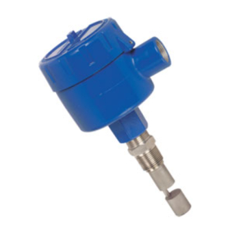
Summary of Contents for Omega Engineering LVU-230
- Page 1 User’ s Guide LL-100 Series Shop online at omega.com e-mail: info@omega.com For latest product manuals: omegamanual.info LVU-230 LVU-260 LVUC10 Ultrasonic Point Level Switches...
- Page 2 OMEGAnet ® Online Service omega.com Servicing North America: U.S.A.: One Omega Drive, P.O. Box 4047 ISO 9001 Certified Stamford, CT 06907-0047 TEL: (203) 359-1660 e-mail: info@omega.com Canada: 976 Bergar Laval (Quebec) H7L 5A1, Canada TEL: (514) 856-6928 e-mail: info@omega.ca For immediate technical or application assistance: U.S.A.
-
Page 3: Unpacking Instructions
UNPACKING INSTRUCTIONS Remove the Packing List and verify that you have received all equipment, includ- ing the following (quantities in parentheses): Ultrasonic Level Switch (1) Operator’s Manual (1) If you have any questions about the shipment, please call the Omega Customer Service Department. -
Page 4: Table Of Contents
TABLE OF CONTENTS Chapter 1 Point Level Model Description ..... . .4 Chapter 2 Principles of Operation ......5 Chapter 3 Installation . -
Page 5: Point Level Model Description
Its small size standard 3/4” NPT mounting fitting, and ability to be installed vertically or horizontally makes it the perfect choice for new or existing applications. MODEL FUNCTION LVU-230 Standard Point Level Gap Sensor LVU-260 Loop Power Point... -
Page 6: Principles Of Operation
(see appropriate wiring diagram for your unit). 3. Apply power from the source. 4. Place the sensor in the liquid. The relay should energize, or output will switch to 20.0±1.0mA. 5. Remove the sensor from the liquid. The relay will de-energize or output will switch back to 4.0±1.0mA indicating that the system is functioning properly. -
Page 7: Final Installation
FINAL INSTALLATION CONTACT MODELS Follow the instructions below: 1. Drill a suitable hole in the vessel or pipe wall and tap for 3/4” NPT. If this walled vessel or material is not suitable for threading, weld or braze a bush- ing to accept the sensor. -
Page 8: Calibration Procedure
5. Allow the liquid or sludge to fall below the sensing point, relay should be de- energized or output will switch back to 4.0+1.0 mA. If not, turn the poten- tiometer counter clockwise until the relay is de-energized. Turn the poten- tiometer counter clockwise one half turn. -
Page 9: System Wiring Diagram
SYSTEM WIRING DIAGRAM For Ultrasonic Point Level Switches... - Page 10 SYSTEM WIRING DIAGRAM For Ultrasonic Point Level Switches...
- Page 11 SYSTEM WIRING DIAGRAM For Ultrasonic Point Level Switches...
-
Page 12: Dimensional Drawings
DIMENSIONAL DRAWINGS For Ultrasonic Point Level Switches... - Page 13 DIMENSIONAL DRAWINGS For Ultrasonic Point Level Switches...
-
Page 14: Maintenance
MAINTENANCE PREVENTATIVE MAINTENANCE Electronics are constructed with solid state components and are epoxy encapsu- lated. Periodically check and clean the sensor when used with liquids which cause a coating build up on the sensor. No other maintenance is required. CLEANING If the pipe or vessel to which the unit is mounted is to be steam cleaned or cleaned with abrasive detergents, remove the entire unit before cleaning by: 1. - Page 15 WARRANTY/DISCLAIMER OMEGA ENGINEERING, INC. warrants this unit to be free of defects in materials and workmanship for a period of 13 months from date of purchase. OMEGA’s WARRANTY adds an additional one (1) month grace period to the normal one (1) year product warranty to cover handling and shipping time. This ensures that OMEGA’s customers receive maximum coverage on each product.
- Page 16 Where Do I Find Everything I Need for Process Measurement and Control? OMEGA…Of Course! Shop online at omega.com TEMPERATURE Thermocouple, RTD & Thermistor Probes, Connectors, Panels & Assemblies Wire: Thermocouple, RTD & Thermistor Calibrators & Ice Point References Recorders, Controllers & Process Monitors Infrared Pyrometers PRESSURE, STRAIN AND FORCE Transducers &...


Need help?
Do you have a question about the LVU-230 and is the answer not in the manual?
Questions and answers