Table of Contents
Advertisement
Advertisement
Table of Contents

Summary of Contents for SPEED LEADER LVP-1000
- Page 1 LED Video Processor User Manual Model: LVP-1000/1000S...
-
Page 2: Table Of Contents
Table of Contents Statement ..........................1 About This Manual ......................1 Trademark Credit ........................ 2 Safety Instructions ....................... 3 Accessories ......................... 4 Function information ......................6 Ports and specificaitons ....................... 8 Installation ........................10 Installation of LED Transmission Card ................11 Front panel ........................ -
Page 3: Statement
Representation Without written permission of the Company, no unit or individual may imitate, reproduce or copy this Manual, in full or in part. This Manual shall not be distributed or used for any commercial purposes in any form (electronic, mechanical, photocopy, recording or other possible forms). -
Page 4: Trademark Credit
Trademark Credit VGA and XGA are the registered trademarks of IBM. VESA is the trademark of Video Electronics Standards Association. The HDMI logo and High-Definition Multimedia Interface are the trademarks of HDMI Licensing LLC. -
Page 5: Safety Instructions
Safety Precautions The device is designed for indoor . For outdoor use, please take precautions. The device needs to use voltage with rated power. The error of input voltage must be ± 10%. Never use the device in a place with the altitude over 3048m. ... -
Page 6: Accessories
Accessories Open the package carefully, and check whether the following objects are contained in it. If any accessory is lacked, contact the seller. AC power cable 1 pcs (for 100-240 V) Connected to the AC power connector to supply power to this device. - Page 7 LED Sending Card (optional) SDI Module (optional) Flightcase (optional) User Manual Reference for the user purchasing or using the device. Qualified Certificate certificate that proves the product passes strict quality inspection. Warranty Card Product after-service recording card, with which, the after-service provided by the Company can...
-
Page 8: Function Information
Function Information LVP Series Video Processor is a high performance LED video processor that uses the 30-bit bital signal processing technology, advanced deinterlacing signal processing and real Seamless Switch technology for professional demonstration. It supports 1080p and 1920x1200@60Hz full HD resolution output (up to 2304X1152@60Hz). Point-to-point pixel adjustment can be realized. - Page 9 A number of test patterns are provided, including square, color bar, gray-scale, alternating pixel, white field, red, green, and blue test patterns. Picture-in-picture Any Size Any Position The position, size, transparency, border width, color, ,border,etc. of picture-in-picture can be adjusted and controlled at will. Broadcast Quality Image Scaling Engine The LVP1000 Video Processor adopts the high performance 30-bit Faroudja®...
-
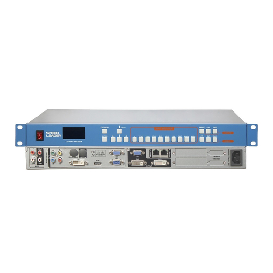
Page 10: Ports And Specificaitons
Ports and Specifications Ports are the important parameters the user should understand before the installation. By understanding the ports, the user can install and set up the device rapidly and avoid problems. The following are the definitions and specifications of the ports on the back of the video processor. - Page 11 ⑩ VGA1 Input VESA standard, PC to 1920x1200@60Hz ⑪ VGA2 1024× 768@60Hz ⑫ 1536× 1536@60Hz 1280× 720@60Hz 2048× 640@60Hz 1280× 1024@60Hz 2048× 1152@60Hz 1440× 900@60Hz 2304× 1152@60Hz Output 1600× 1200@60Hz ⑬ DVI1 2560× 816@60Hz 1680× 1050@60Hz 1280× 720@50Hz 1920× 1080@60Hz 1920×...
-
Page 12: Installation
Installation Before the installation, please check whether the installation components are complete and carefully read the Safety Precautions and the Ports and Specifications. Humanized treatment is used for the ports of the video processor, with a box indicating the input ports and a box indicating the output ports. -
Page 13: Installation Of Led Transmission Card
Installation of LED Transmission Card 1. Remove the upper cover and then the baffle of the case and install the fixing bolts at the corresponding positions so as to install the transmission card of the corresponding brand. 2. Install the LED transmission card, fix it with the 4 screws supplied, tighten the hexagonal bolt of the DVI interface, and insert the 4PIN, 5V power cable into the power socket of the transmission card, as shown in the figure. -
Page 14: Front Panel
Front panel The Front Panel of the video processor uses a friendly human machine interface and clear and simple LCD menu displaying. The default menu displays the operation modes of the video processor for you, and you can use the main menu to set detailed parameters. The panel provides the most frequently used shortcut keys with LED indicator inside (except menu operation keys) to indicate the operation mode of the current function. - Page 15 In the function menu, the various parameters can be adjusted. Left: -; right: + Main channel signal selection shortcut key (7 video interfaces and 3 audio interfaces) HDMI and SDI decode sound output. INPUT ⑤ TEST Outputs test patten SELECTION BLACK Outputs black screen Select external audio or sound for various video...
-
Page 16: Menu
Menu Use the LCD menu system to set the device quickly and intuitively, thus meets your use requirements. When you do not operate or your operation is time-out, the LCD will display the default menu. If you use the keys on the Front Panel to set the device, the LCD will display the corresponding menu according to your operation in order to prompt you and in order for better, quicker and more intuitive operation. - Page 17 ④ Multi-device interconnection mode; output resolution 1600x1200@60Hz In the default menu, the LCD displays the icons of the various functions. The meanings of the icons are described in the table below: Name Description Icon Indicates the information and mode of the current main Main channel input channel input.
-
Page 18: Main Menu
Main Menu When you press the “EXIT/MENU” key, the video processor will enter the main menu mode and the LCD will display the following screen. Use the “EXIT/MENU”, “ AUTO”, “ ”, “ ”, “ ” and “ENTER” keys to select and adjust the various options. IMGE FUNC... -
Page 19: Structure Of Main Menu
Structure of Main Menu Image Mode, Brightness, Contrast, Color, Sharpness, Color TEMP, User CT, Gamma, Contrast PT,ACM Manage, IMAGE Motion Mode, BLK Extend, DNR, MPEG NR, Film Mode, Reset Full H Total, V Total, H Start, V Start, V-Wall Tuning, Reset Crop Resolution, Width, Height, H Start, V Start, Reset Input, Frame Color, Frame Size, Blender,... -
Page 20: Function Description
The menu is operated in a fixed mode, as shown in the table below Operation In the default menu, press the “EXIT/MENU” key. Open main menu Press the “EXIT/MENU” key. Exit main menu Select Press the “ AUTO” or “ ” key. Press the “... -
Page 21: Crop
Crop The fusion function is a solution used to solve the restriction of a single video processor’s being unable to drive an ultra big LED. The ways of fusion are flexible. The fusion function can be applied in various LED fusion systems. Signal Connection The Crop function uses one input signal splicing unit, that is, a channel can use a signal source only (signal loop out or signal distribution input may be used), and outputs video on... -
Page 22: Crop Setup
Crop Setup After the device is connected, set the corresponding output resolution and Crop method according to the LED wall. Set output resolution: On the main menu, select “Output” → “Output Resolution” → Resolution, select the appropriate resolution, and press the “ENTER” key. Set Crop method: On the main menu, select “CAP”... -
Page 23: Pip Mode
Vertical Total Pixels form a coordinate plane with pixel as scale. The processor sets the desired parameters “H Start” and “V Start” according to the coordinate plane. The PIP function includes the Picture-in-Picture mode and KEY mode. When the function is turned on, the “Seamless Switching” function will be turned off automatically. PIP Mode The PIP mode is Picture-in-Picture that uses the bital technology to display two programs on the same screen, that is, on the main screen being watched normally, one or more... -
Page 24: Keying Mode
Enter PIP menu: In the main menu, select “PIP” → “PIP Mode” → Parameter Setup and set the parameters of the PIP mode. Note: To select the input signal channel of PIP, you must select in the “PIP Mode” menu. There is no shortcut key. -
Page 25: Seamless Switch
PIP Channel + Main Picture Channel = Caption Effect The above figure shows that the PIP channel input is a picture of white text in the blue background, and when the two pictures are overlaid and the blue color is removed, the caption effect is realized. -
Page 26: Preset Mode
test patten output: On the Front Panel, press “TEST” to output the current patten; press “TEST” again and use the direction keys to select different test patten. Preset Mode In the preset mode, you can quickly invoke various frequently used application scenarios during use to reduce repeated, complex setup, thus improves the efficiency of operations. -
Page 27: Mult-Device
Multi-device The purpose of Multi-device interconnection is to control multiple machines simultaneously through a LED video processor to realize displaying on the same large display or displaying of multiple independent LED walls, with each processor realizing input and output of multiple video signals. The advantage of Multi-device interconnection is that when any device is operated, the concatenated devices will act simultaneously. -
Page 28: Multi-Device Connection
Multi-device Connection The figure below is the sketch map of Multi-device interconnection realized by 3 LED walls. The premise of Multi-device interconnection is the simultaneous communication between devices. Therefore, the devices should be concatenated to realize a closed loop. The rear panel of the video processor has two RS232 communication ports: REMOTE TX (transmission) and REMOTE RX (receiving). - Page 29 Just operate any device, and you can realize all above functions of Multi-device interconnection. Through the shortcut keys on the Front Panel, you can control the interconnected devices quickly. The following is the list of active keys and functions in the interconnection mode: List of Keys Available in the Interconnection Mode Functions...
-
Page 30: Audio Switching
Audio Switching LVP-1000 has 3-channel audio switching, including external audio, HDMI audio, and SDI audio. The processor can realize 3 audio switching modes, i.e. Fixed External Input, Sound Channel Following, and Audio Off. Press the “AUDIO” key repeatedly to switch between these 3 modes. -
Page 31: Troubleshooting
Troubleshooting Problems may occur during installation or use. The user can try to troubleshoot the device through the following steps. If the problem still cannot be solved, the user can contact the local dealer. Phenomenon Solution The device has no Check whether the power plug is in bad contact. - Page 32 displayed on the full screen. Video are not displayed Check whether the resolution and refresh rate input are normally. compliant. The displaying of PIP Check whether the PIP parameters are set correctly and is abnormal. reasonably. The Seamless Switch Check whether the current mode is PIP mode. Disable the PIP function does not work.
- Page 33 I n d u s t r y S a le s a n d S e r v ic e H o t l i n e : 4 0 0 - 6 2 8 6 - 9 5 9 深...
Need help?
Do you have a question about the LVP-1000 and is the answer not in the manual?
Questions and answers