Table of Contents
Advertisement
Frosty Factory
of America, Inc.
2301 S. Farmerville St., Ruston, LA 71270
frostyfactory.com
(318) 255-1162
(800) 544-4071
(318) 255-1170 fax
Service Manual
All technical data, pictures and drawings contained in this manual are not binding on the
manufacturer nor can the manufacturer be held liable for any modifications to the machine in whole
or in part.
Revised 1/2016
1
Advertisement
Table of Contents

Related Manuals for Frosty Factory 127

Summary of Contents for Frosty Factory 127
- Page 1 Frosty Factory of America, Inc. 2301 S. Farmerville St., Ruston, LA 71270 frostyfactory.com (318) 255-1162 (800) 544-4071 (318) 255-1170 fax Service Manual All technical data, pictures and drawings contained in this manual are not binding on the manufacturer nor can the manufacturer be held liable for any modifications to the machine in whole or in part.
-
Page 2: Table Of Contents
TABLE OF CONTENTS 1.0 INTRODUCTION 1.1 Use of the Manual 1.2 Preliminary Inspection 1.3 Description 1.4 Dimensions 2.0 LOCATION AND INSTALLATION 2.1 Safety Precautions 2.2 Installation 3.0 OPERATION 3.1 Machine Controls 3.2 The Product You Serve 3.3 Product Consistency 3.4 Start Up 3.5 Freeze Time 4.0 MAINTENANCE 4.1 Cleaning... -
Page 3: Introduction
All machines are shipped FOB Ruston, Louisiana, which means that the machines left our docks in perfect working order. Frosty Factory of America is not responsible for damaged merchandise once the equipment leaves our dock. Inventory the accessories to be sure they include the items you specified on your order. -
Page 4: Description
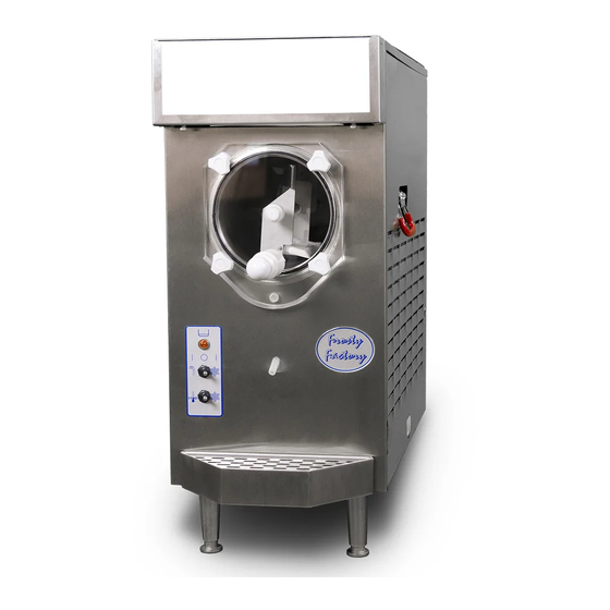
1.3 DESCRIPTION Stainless Lighted Steel Cabinet Flavor Sign Stainless Beater Bar Steel C6530 Cylinder Scraper Blade C6510 Faceplate Knobs F0262 Faucet Assembly Clear Plastic C6513 Faceplate C6521 Drip Tube Fill Indicator Light F0207 Drip Tray Insert F6604 Control Switches F0416 Drip Tray Bottom F0417 F6603... -
Page 5: Location And Installation
SECTION 2 LOCATION & INSTALLATION 2.1 SAFETY PRECAUTIONS Do not attempt to operate your Frozen Drink Machine until the safety precautions and operating instructions in this manual are read completely and are thoroughly understood. 2.2 INSTALLATION Placing your Frozen Drink Machine in a highly visible area will enhance sales. CAUTION: Do not attempt to share the dedicated electrical outlet with any other appliance;... - Page 6 NOTICE: Locating the unit in direct sunlight, near cooking equipment or any high heat area will reduce the performance of your machine. CAUTION: Extended operations under severe heat condition can damage the cooling system. NOTICE: Establishments that serve beverages from frozen drink machines are responsible for providing the necessary facilities for cleaning and sanitizing their food service equipment.
-
Page 7: Operation
SECTION 3 OPERATION 3.1 MACHINE CONTROLS Two selector switches located on the front of the machine control operation of the Frozen Drink Machine. Selection of the right (snowflake) position, with both switches, will schedule the machine for normal operation. The compressor cycle is protected by a time delay circuit, which will engage the compressor approximately 2 minutes after normal operation is initiated. -
Page 8: The Product You Serve
3) Keep the machine clean - ALWAYS! beverage thicker 3.3 PRODUCT CONSISTENCY An exclusive, patented, torque consistency control (TCC) developed by Frosty Factory of America will allow for consistent texture and thickness adjustments of your frozen beverages. The adjustment screw (accessible through the left side panel) is pre-set at the factory. -
Page 9: Start Up
3.4 START UP NOTICE: Before start-up, be sure the machine has been sanitized in accordance with procedures set forth in the cleaning section of this manual. Pour the mix into the hopper and allow it to drain into the cylinder. Fill the Hopper Do not run the... -
Page 10: Maintenance
SECTION 4 MAINTENANCE 4.1 CLEANING The following cleaning procedure should be used for initial start-up and on an as needed basis to comply with the minimum cleaning and sanitizing frequencies specified by the federal, state or local regulatory agency having jurisdiction. (1.) Turn the machine to the off, “hand”... -
Page 11: Re-Assembly
4.2 RE-ASSEMBLY F0298 (1) Hand wipe all surfaces to remove any remaining residue on the machine, then: using Petro-Gel (or other sanitary food grade lubricant), lightly lubricate the longer end of the beater shaft. Slide beater seal onto the shaft with the spring end toward the beater bar. -
Page 12: Preventative Maintenance
(5) Mix two gallons of warm water with one 2 oz. packet of sanitizer. (6) Pour two gallons of solution into hopper. Clean the hopper and feed hole with a clean sanitized brush. (7) Place upper switch in “faucet” position. Let solution stir for 5 minutes. Turn upper switch “OFF”... -
Page 13: Troubleshooting
4.5 TROUBLESHOOTING Machine does not run when turned on. Be sure that the plug is properly installed in wall outlet. Be sure that the faceplate is installed Check and reset circuit breaker if necessary. Be sure that no other appliances are sharing the circuit. Beater motor starts but compressor doesn’t start. - Page 14 9. Beater bar does not turn. Faceplate not installed. Install faceplate. Mix is frozen solid. Low sugar content, product separation or cylinder not full. Drive coupling stripped. Drive coupling needs to be replaced Faulty motor. Replace motor 10. Mix turns grey or pitting metal in the freezing barrel Too much chlorine in sanitizing solution: Follow directions on product package to get 100 parts/million chlorine solution.
-
Page 15: Rear Cylinder And Drive Assembly Parts List
4.6 REAR CYLINDER AND DRIVE ASSEMBLY PARTS LIST Model 127. Description Part Number 1. Ceramic Seal F0665 2. Bearing Spacer Block C2316B 3. Coupling Bearing F0427 5/16” 4. Flat Washer 5. Nut 5/16-18 6. Drive Coupling C0907 Motor F1210 Drive... - Page 16 4.7 FACEPLATE / FAUCET ASSEMBLY Faucet Assembly C6513. Align Faucet Assembly opening to Teflon Tape added bottom of faceplate then tighten nut before installation Installing O-rings onto plunger F 0491 Lubricating O-rings with Petro-Gel F0298 Installing Plunger Installing faceplate C6521 assembly C6513P onto front of Machine.
-
Page 17: Faceplate And Faucet Assembly
4.7 FACEPLATE/FAUCET ASSEMBLY (cont.) Face Plate/Faucet Assembly Part No. A. Face plate assembly with magnet C6521 B. Faucet assembly with nut C6513 C. Plunger Assembly (only) C6513P D. Faucet body (only) C6513B Plunger Assembly C6513P Knob O-Rings Face Plate F0264 F0491 C6521 O-Ring... -
Page 18: Float Switch Assembly
4.8 FLOAT SWITCH ASSEMBLY 1. The float switch assembly consists of: Post switch, Float , Float clip, O-Ring and Nut. 2. There are two dots (or raised ring) on one end of the float. When assembled the two dots or raised ring, must be on the top end of the float. Clip Fill Switch Assembly F0811 Raised ring must point up... - Page 19 Water-Cooled Option on 127W ONLY Water Bracket Assembly (Exploded View) Fitting, Water Hose F6100 Fitting, Bulkhead Water Star Washer F6101 Frame Bracket, (Water/Refrigeration) F0200 1. Insert the water bulkhead fitting P.N. F6101 through the bracket hole. 2. Place the star washer over the threaded portion of the bulkhead fitting. 3.
- Page 20 Water-Cooled Option on 127W ONLY Water Cooled System There are two water fittings at the rear of the frame. 1. The system uses standard washing machine hoses. 2. Water-in, Water-out fittings located at rear of machine frame. 3. Scale build-up will occur in pipes when outlet temperatures rises above 95°F.
-
Page 21: Using The Cleaning Brushes
4.10 USING THE CLEANING BRUSHES Drip Chamber Ceramic Seal Q Tip For cleaning Cylinder Drip Tube Drip tube Brush F6526 Bearing Spacer Block C2316B Push brush all the way in until it can be seen behind Insert long brush the ceramic ring F6526 into drip tube... -
Page 22: Scraper Blade And Spring Seal Installation
4.11 SCRAPER BLADE AND SPRING SEAL INSTALLATION Step 1: Attach scraper blade spring F6517as shown. Step 2: Insert rod end into beater bar frame. Step 3: Tap scraper blade rod until it is centered. Step 4: Apply a small dab of Petro-Gel F0298 Step 5: Install spring seal F0355 Step 6: Squeeze and... -
Page 23: Beater Seal Assembly
4.12 SPRING SEAL ASSEMBLY DETAIL 1. Using Petro-Gel (or other sanitary food grade lubricant), lightly lubricate the longer end of the beater shaft. Slide beater seal onto the shaft with the spring end toward the beater bar. (Refer to diagram in this section of your manual or on top of the hopper cover for correct installation of spring seal). - Page 24 4.13 CERAMIC SEAL REMOVAL AND REPLACEMENT Note: Use this procedure only when necessary to replace a damaged ceramic seal To remove old seal; 1. Press the “Push button” on the puller tool to release the ball bearings. 2. Insert “T” handle through ceramic seal at rear of Notice: Do cylinder.
-
Page 25: Spare Parts List
5.0 SPARE PARTS LIST 127A Rev. 08/07/07 DESCRIPTION ITEM NUMBER Air Condenser F127 Bearing Spacer Block C2316B Bearing, Coupling F0427 Beater Bar C6530 Beater Bar Spring Seal F0355 Compressor, ¾ H.P.115/60/1 F8053 Run Capacitor F0135 Start Capacitor F0213 Start Relay F0371 Compressor, ¾... - Page 26 DESCRIPTION ITEM NUMBER O-Ring, Face Plate F0357 O-Ring, Faucet F0491 O-Ring, Fill Switch F0161 Petro-Gel F0298 Puller Tool F0012 Rear Bearing Carrier C1201 Rear Panel F123 Rear Support Bearing F0476 Right Side Panel F120 Sanitizer F0492 Scraper Blade C6510 Scraper Blade Spring F6517 Sign Panel, Clear F1226...
-
Page 27: Factory Assistance
If you must call the factory for assistance; Locate the Model and Serial Numbers, of your machine, on the data plate on the back panel; have this information available before you contact the factory. Frosty Factory of America Inc. 2301 So. Farmerville St. Ruston, La. 71270... -
Page 29: Wire Drawing
127 WIRE DRAWING 2009 Contactor Contactor Time Delay Motor Interlock Relay Run Cap Flavor Condensor Freeze- Off- Light Wash Switch Compressor Start Freeze- Standby Switch Start Relay Standby Thermostat H-P Switch Micro Switch 20 uf Motor Motor Safety Capacitor Interlock... - Page 30 Compressor wiring 127A Wht from cord Blk from cord Relay Black Grn from cord White Start Compressor Cap. Cap. Terminals...
-
Page 31: Warranty
(at its option) without cost to purchaser-user except transportation charge any part or parts of said unit proved to the satisfaction of Frosty Factory of America, Inc. to be defective when sold. The warrantor shall not be responsible for any expenses incurred for service or repairs performed by a person or entity other than the Warrantor, unless specifically authorized by the Warrantor, and the repair falls in the 1 year labor warranty period.
Need help?
Do you have a question about the 127 and is the answer not in the manual?
Questions and answers