Advertisement
3
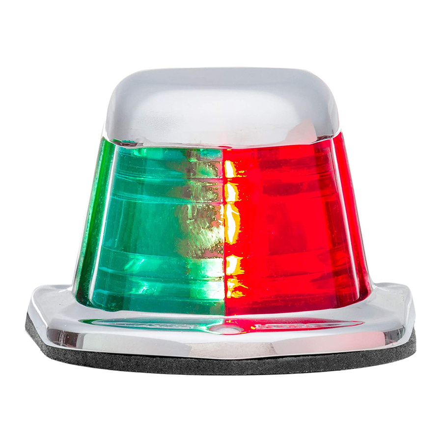
12-Volt Stainless 1-Mile
Navigational Light
Without Wire Leads: 66320
With 7" Wire Leads: 66318, 66319
Attwood marine hardware, navigational lighting, bilge pumps, and other
marine accessories are specified more than any other brand by America's
best-known boat manufacturers as original equipment. Look to Attwood
for quality replacement parts and marine accessories.
SAVE THESE INSTRUCTIONS
Form Number 69376 Rev. B
FEATURES
The Attwood 12-volt DC stainless steel one-mile navigational
sidelights are designed for mounting on horizontal surfaces, such
as the gunwale or deck. Meets USCG CFR 183.810, ABYC A-16
requirements, and all applicable standards as tested by ITS (ETL),
5/23/1995. 1 Nautical Mile visibility. Uses Lamp 9231, 12V, 8 Watt.
The housing is made of highly-polished stainless steel for corrosion
resistance. The lens completely encapsulates the bulb and socket
assembly for splash resistance. The lens rests on a rubber gasket,
making these lights virtually waterproof when used with the optional
base gasket.
REQUIRED FOR INSTALLATION
• #1 Phillips head screwdriver.
• Drill with suitable bits —
• Base gasket (Attwood # 910410) or marine sealant.
• Three #4 or #6 stainless steel pan head screws.
LOCATION
1. Be sure that sidelights shine straight ahead. Combination sidelight
must be aligned on centerline (See Figure 1a), sidelights pairs must
be parallel to centerline (See Figure 1b.)
2. Position light(s) on a horizontal surface ( 5 ) of the gunwale or
deck. If installing a combination light, place it on the furthermost
tip of the bow on the centerline of the boat. (See Figure 1a.)
Sidelight pairs must be equal distance from the bow. The red lens
must be on the port (left) and the green on the starboard (right) as
you stand onboard facing the bow of the boat. (See Figure 1b.)
Figure 1a
112.5 Arc Must Be Clear
Red
Green
(Port)
(Starboard)
3. Ensure that there are no front or side obstructions, such as rail
stanchions, chocks, anchors, etc., within the arc of visibility
(112.5 each side).
®
03-10
" (13mm).
Figure 1b
Red
Green
(Port)
(Starboard)
4. Measure and mark location of terminal clearance hole. Hole(s)
must be on boat centerline for combination sidelight (66318,
Figure 1a), or equal distance from bow for sidelight pairs (66320
and 66319, figure 1b.) Drill a
Figure 2
•
•
•
•
•
27/32"
2-1/4"
(56mm)
(57mm)
•
1-11/16"
(27mm)
•
•
•
7/8"
(22mm)
MOUNTING INSTRUCTIONS
1. Place base into hole and align so that light(s) shine straight
ahead. Use base to mark pilot holes for the mounting screws.
Drill pilot holes.
2. Feed the power source leads up through the deck and attach to
base terminals or wires. Insulated terminals are recommended.
3. Apply base gasket or sealant to the deck mounting area. Gasket
is highly recommended on aluminum surfaces. Place gasket, then
lens, and housing over the base.
CAUTION
Position carefully on aluminum boats so that wires do not contact
the hull.
4. Insert mounting screws through housing and fasten into deck.
(See Figure 3.)
Figure 3
" (13mm)-dia. hole. (See Figure 2.)
2-1/2"
(64mm)
•
2-1/16"
•
(52mm)
Centerline
•
1/2" Dia.
•
(13mm)
Screws
(Not Supplied)
•
Housing
•
Lens
•
Gasket
•
Bulb
Centerline
of Boat
•
Base
•
•
Advertisement
Table of Contents

Subscribe to Our Youtube Channel
Related Manuals for Attwood 66318


Summary of Contents for Attwood 66318
- Page 1 (112.5 each side). 4. Measure and mark location of terminal clearance hole. Hole(s) must be on boat centerline for combination sidelight (66318, Figure 1a), or equal distance from bow for sidelight pairs (66320 and 66319, figure 1b.) Drill a Figure 2 •...
- Page 2 Attwood’s obligation under this warranty is limited to repair of the product at Attwood’s plant or replacement of the products at Attwood’s option without expense to the original consumer purchaser.
Need help?
Do you have a question about the 66318 and is the answer not in the manual?
Questions and answers