
Summary of Contents for RDL SIM900A
- Page 1 GSM GPRS SIM900A MODEM REV1.0 GPRS /GSM SIM900A MODEM WITH ARDUINO COMPATIBLE USER MANUAL www.researchdesignlab.com Page 1...
-
Page 2: Table Of Contents
Minimum Functionality Mode ....................9 Sleep mode ..........................9 Wake up SIM900A from sleep mode ..................9 PINS OF GPRS /GSM SIM900A MODEM WITH ARDUINO COMPATIBLE ....... 10 NARATION OF GPRS /GSM SIM900A MODEM WITH ARDUINO COMPATIBLE ... 11 BLOCK DIAGRAMS ........................12 INTERFACING UNO AND GSM SHIELD ................ -
Page 3: Overview
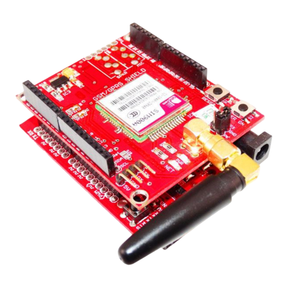
GSM GPRS SIM900A MODEM REV1.0 Overview GPRS /GSM SIM900A MODEM WITH ARDUINO COMPATIBLE This is a very low cost and simple Arduino GSM and GPRS shield. We use the module SIMCom SIM900A. The Shield connects your Arduino to the internet using the GPRS wireless network. Just... -
Page 4: Features
GSM GPRS SIM900A MODEM REV1.0 Features Dual-Band GSM/GPRS 900/ 1800 MHz. RS232 interface for direct communication with computer or MCU kit. Configurable baud rate. Power controlled using 29302WU IC. ESD Compliance. Enable with MIC and SPeaker socket. -
Page 5: Basic At Commands For Testing
GSM GPRS SIM900A MODEM REV1.0 Basic AT Commands for Testing GSM AT Commands: TO CHECK THE MODEM: ↲ TO CHANGE SMS SENDING MODE: AT+CMGF=1 ↲ TO SEND NEW SMS: AT+CMGS=”MOBILE NO.” ↲ <MESSAGE {CTRL+Z} TO RECEIVE SMS AT+CMGD=1 ↲... -
Page 6: Gprs Commands
GSM GPRS SIM900A MODEM REV1.0 AT+CRC SET CELLULAR RESULT CODES FOR INCOMING CALL INDICATION: AT+CRC=? ↲ +CRC: (0-1) AT+CRC? ↲ +CRC: 0 AT+CRC=1 ↲ +CRING: VOICE READ OPERATOR NAMES. AT+COPN=? ↲ AT+COPN ↲ +COPN: “472001″,”DHIMOBILE” +COPN: “60500 +COPN: “502012″,”maxis mobile”... -
Page 7: Module Setup
GSM GPRS SIM900A MODEM REV1.0 MODULE SETUP step 1 : Insert SIMcard into the SIM slot. step 2 : power ON through Controller (Place Jumper on JP4 of GSM shield) step 3 : power ON automatically (Place Jumper on JP3 of GSM shield) www.researchdesignlab.com... -
Page 8: Sample Code
GSM GPRS SIM900A MODEM REV1.0 step 4 : Press and hold power button (To turn on manually without jumper) step 5 :compile and burn the sample code given below to UNO board and then mount the GSM Shield. SAMPLE CODE: void setup() Serial.begin(9600);... -
Page 9: Power Modes
Wake up SIM900A from sleep mode Enable DTR pin to wake up SIM900A. If DTR pin is pulled down to a low level This signal will wake up SIM900A from power saving mode. The serial port will be active after DTR changed to low level for about 50ms. -
Page 10: Pins Of Gprs /Gsm Sim900A Modem With Arduino Compatible
GSM GPRS SIM900A MODEM REV1.0 PINS OF GPRS /GSM SIM900A MODEM WITH ARDUINO COMPATIBLE www.researchdesignlab.com Page 10... -
Page 11: Naration Of Gprs /Gsm Sim900A Modem With Arduino Compatible
GSM GPRS SIM900A MODEM REV1.0 NARATION OF GPRS /GSM SIM900A MODEM WITH ARDUINO COMPATIBLE www.researchdesignlab.com Page 11... -
Page 12: Block Diagrams
GSM GPRS SIM900A MODEM REV1.0 BLOCK DIAGRAMS INTERFACING UNO AND GSM SHIELD *Atmega 328 must be powered with DC 12v 2A. www.researchdesignlab.com Page 12... -
Page 13: Interfacing Microcontroller With Gsm Shield External Serial Pins
GSM GPRS SIM900A MODEM REV1.0 INTERFACING MICROCONTROLLER WITH GSM SHIELD EXTERNAL SERIAL PINS www.researchdesignlab.com Page 13... -
Page 14: Code
GSM GPRS SIM900A MODEM REV1.0 CODE GSM POWER SAVING PIC CODE http://researchdesignlab.com/gsm-power-pic-code.html www.researchdesignlab.com Page 14... -
Page 15: Module Handling
GSM GPRS SIM900A MODEM REV1.0 MODULE HANDLING DO'S AND DONT'S www.researchdesignlab.com Page 15...
Need help?
Do you have a question about the SIM900A and is the answer not in the manual?
Questions and answers