Table of Contents
Advertisement
Quick Links
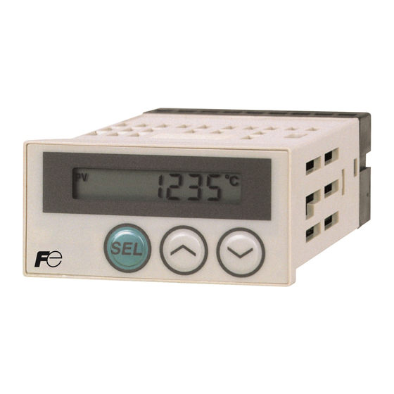
DIGITAL THERMOSTAT
Model : PAS3
Thank you for your purchasing "Fuji DIGITAL THERMOSTAT." Please check that the product is exactly the
one you ordered and use it according to the following instructions. (Please refer to a separate operation
manual for details.) Dealers are cordially requested to ensure the delivery of this Instruction Manual to hands
of the end-users.
NOTICE
The contents of this document may be changed in the future without prior notice.
We paid the utmost care for the accuracy of the contents. However, we are not liable for direct and indirect
damages resulting from incorrect descriptions, omission of information, and use of information in this docu-
ment.
Safety Precautions ............................................... 2
For normal usage ................................................. 7
1. Installation/mounting ...................................... 8
2. Wiring ............................................................. 9
3. Usage ............................................................. 10
4. Operation ....................................................... 11
Check of specifications and accessories
Before using the controller, check if the type and specifications are as ordered.
Check that all of the following accessories are included in the package box.
· Digital thermostat mian unit
· Instruction manual
· Mounting bracket
· Watertight packing
· Thermister sensor (only for the type that the input signal is thermistor)
Note: The provided thermistor sensor is the sensor dedicated to this equipment.
Details for operation method and the related documents
Contents
Operation method
Details of alarm functions
Specifications
Instruction Manual
Instruction Manual
INP-TN1PAS3-E
CONTENTS
DIGITAL THERMOSTAT OPERATION MANUAL
DETAIL DESCRIPTION ABOUT FUNCTIONS
OF ALARM OF DIGITAL THERMOSTAT
Catalogue
Head Office
11-2, Osaki 1-chome, Shinagawa-ku, Tokyo, 141-0032 Japan
Sales Div. International Sales Dept.
No.1, Fuji-machi, Hino-city, Tokyo, 191-8502 Japan
Phone : +81-42-585-6201, 6202
Fax : +81-42-585-6187, 6189
http://www.fic-net.co.jp
5. Display shifting method .................................. 12
6. Functions ....................................................... 13
7. List of parameters .......................................... 15
8. Alarm function ................................................ 17
9. Error indications ............................................. 19
Specification ......................................................... 19
PAS3 Model Code ................................................ 19
1 unit
1 copy
1 pce.
1 pce.
Name
- 1 -
No.
ECNO:410
TN513439-E
ECNO:1142
Advertisement
Table of Contents

Related Manuals for Fuji Electric PAS3

Summary of Contents for Fuji Electric PAS3
-
Page 1: Table Of Contents
9. Error indications ..........19 4. Operation ............11 Specification ............19 PAS3 Model Code ..........19 Check of specifications and accessories Before using the controller, check if the type and specifications are as ordered. Check that all of the following accessories are included in the package box. -
Page 2: Safety Precautions
Safety Precautions Before using this product, the user is requested to read the following precautions carefully to ensure the safety. Safety precautions must be taken by every user to prevent accidents. The safety requirements are classified into “warning” and “caution” according to the following interpreta- tions: Suggesting that the user's mishandling can Warning... -
Page 3: Installation And Wiring
Warning 1.1 Installation and wiring 0 to + 50 [°C ] Operating temperature Operating humidity 90%RH or less (Non condensation) Installation category Conforming to IEC1010-1 Pollution degree • This product designed to be installed at the conditions shown in the right table. •... - Page 4 Caution 2.1 Cautions on installation Avoid the following places for installation. • A place where the ambient temperature may reach beyond the range of from 0 to 50°C while in operation. • A place where the ambient humidity may reach beyond the range of from 45 to 85% RH while in operation.
- Page 5 Standard : Vertical mounting, flush on the panel. (This product is horizontal.) When mounting this product on tilted surface, the maximum tilt angle is 30° (degree) from vertical. – 5 –...
- Page 6 • If inductive load such as magnetic switches connected as a alarm output load, it is recommended to use Z-Trap manufactured by Fuji Electric to protect a contact from switching serge and keep a longer life. Model : ENC241D-05A (power supply voltage: 100 V) ENC471D-05A (power supply voltage: 200 V) Where to install : Connect it between contacts of the alarm output.
-
Page 7: For Normal Usage
For normal usage <Description> <Remarks> <Reference items> • Confirming that the delivered Confirming type specification product is equal to the ordered one. • Outline dimensions Installation/mounting • Read “Safety Precautions” • Panel cutout dimensions • Mounting method on the panel Wiring •... -
Page 8: Installation/Mounting
Installation/mounting Outline and Panel Cutout Dimensions Outline dimensions (Unit : mm) Watertight packing PV SET1 SET2 ALM1 ALM2 Mounting bracket Panel thickness (1 t 8) Panel cutout dimensions (Unit : mm) For separate mounting For mounting close together (n controllers) +0.5 +0.5 a=(48 ×... -
Page 9: Wiring
Wiring Terminal Connection Diagram (100 to 240 Vac) 16 17 Measured value input Alarm output 1 Alarm output 2 Power supply Thermocouple Thermistor ALM1 ALM2 AC100-240V Note 1) Check the power supply voltage before installation. Note 2) Tighten the terminal screw securely with fastening torque of 0.4N·m. Designation of Wiring Material •... -
Page 10: Usage
Usage (Read before using) Name of Functional Parts and Functions SET1 SET2 ALM1 ALM2 Display/Indication Name Function Process value (PV) indicator The lamp is lit while a process value (PV) is displayed. Alarm set value 1 (SET 1) The lamp is lit while an alarm set value 1 is displayed. Alarm set value 2 (SET 2) The lamp is lit while an alarm set value 2 is displayed. -
Page 11: Operation
Operation Parameter setting mode (level 2, level 3, level 4) Set value display Parameter name display The increase/decrease speed changes when key is kept pressed. <Parameter setting procedure> 1) Select a parameter you want to set by pressing the key. 2) Press the key to display the parameter set value. -
Page 12: Display Shifting Method
Display shifting method Operation mode (level 1) Changing of the level 1 indication When indicating the process When indicating the alarm set When indicating the alarm set value 1 (SET 1) value 2 (SET 2) value (PV) Press the once SET1 SET2 Press the... -
Page 13: Functions
Functions [Table 1] Alarm action type code Parameters: PA1, PA2 Code of Alarm Hold function Relay operation Set value Action diagram type at alarm and 2 If activation of either one of alarms is not wanted when 2-point alarm is used, alarm set “0”... - Page 14 [Table 2] Input range, input code Parameters: Pn2, PSL, PSU Code Limiting Indication Input signal Range (°C) of Pn2 resolution accuracy ±3°C Thermo- 1°C 0 to 800 couple ±3°C 1°C 0 to 1200 ±4°C 0 to 1600 4°C ±3°C 1°C 0 to 400 ±3°C 0 to 600...
-
Page 15: List Of Parameters
List of parameters Level Parameter Parameter name Function Default Remarks indication setting Level 2 Alarm set value Set the alarm 1 activation value. Note1 100% 1 setup It may be set within the input range. Table2 Set the alarm 2 activation value. Note1 Alarm set value 2 setup It may be set within the input range. - Page 16 1) If the unit of setup of a parameter is engineering value or deviated engineering value, the val- Caution ue of such a parameter changes accompanying change to PSL and PSU. (Indicated by * Values of input range 100% = PSU, input range 0% = PSL 2) FS (full scale) means the value of PSU - PSL.
-
Page 17: Alarm Function
Alarm function 1) Kinds of alarm Absolute value upper limit alarm or absolute lower limit alarm is available. (For details, see Table 1 Alarm action type codes.) ON delay function Alarm Without ON delay function With ON delay function ON delay setting time Energizing/de-energizing function Alarm judgement Relay output... - Page 18 2) Function of alarm “Detail description about functions of alarm of Digital Thermostat” is prepared. Caution Please inquire us when you use this function. No. Function name Function Parameters to set ① Hysteresis Activation dead zone (hysteresis) may be set at alarm activation. Alarm1 : function Alarm2 :...
-
Page 19: Error Indications
Operating ambient temperature: 0 to 50°C, 90%RH or less (no condensation) Preservation temperature: -20 to 60°C Thermistor sensor: Allowable deviation/±2°C or less, constant value B/3390K±1%, resistance/6kΩ (0°C) PAS3 Model Code Specification Model code Input signal Input range Alarm points 1 point...
Need help?
Do you have a question about the PAS3 and is the answer not in the manual?
Questions and answers