Table of Contents
Advertisement
Quick Links
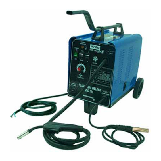
WM 151-C
WELDING MACHINE
OPERATING INSTRUCTIONS
Caution
The manual is the same with skill operator; we request to read the instruction.
People who without training cannot install operating or maintenance the equipment, if
you read and understand the detail rule in this book. You can install or operate, if you
cannot understand, please contact the supplier to get further information.
Advertisement
Table of Contents

Subscribe to Our Youtube Channel
Summary of Contents for ATE Pro. USA WM 151-C
-
Page 1: Welding Machine
WM 151-C WELDING MACHINE OPERATING INSTRUCTIONS Caution The manual is the same with skill operator; we request to read the instruction. People who without training cannot install operating or maintenance the equipment, if you read and understand the detail rule in this book. You can install or operate, if you... - Page 2 Responsibility The user shall inspect the equipment, and faulty equipment shall be stopped. All the faulted, missed, abrasive, distorted and polluted parts shall be changed promptly. When repair or change, the manufacturer advised the user to changed the part forward the require in written or calling form to the licensed distributors.
- Page 3 Safety Warning GENERAL SAFETY Danger means a hazard that will cause death or serious injury if Dang the warning is ignored. Warning means a hazard that could cause death or serious injury Warning if the warning is ignored. Caution means a hazard that may cause minor or moderate injury Caution if the warning is ignored.
- Page 4 Safety Warning Electric arc welding operations cause sparks WARNING and heat metal to temperatures that can cause severe burns! Use protective gloves and clothing when performing any metal working operation. Take all precautions described in this manual to reduce the possibility of skin and clothing burns.
- Page 5 Safety Warning Never wrap arc welder cables around the body. ● Always position the electrode and ground leads so that they are on the same side of the body. ● Exposure to electromagnetic fields during welding may have other health effects which are not ●...
-
Page 6: Chapter 1 Product Description
1.2 Model unit Model WM 151-C Item Rated input voltage Frequency single Phase Max. - Page 7 Chapter 1 Product description 1.4 Equipment condition a) Range of the temperature of the ambient air : During welding: -10℃ to +40℃ After transport and storage at : -25℃ to +55℃ b) Relative humidity of the air : Up to 50% at 40℃ Up to 90% at 20℃...
-
Page 8: Chapter 2 Assembly
Chapter 2 Assembly 2.1 The requirement of installing ground Equal ground is very necessary to the machine, the ground must be have good ventilation system, and can’t be exposed in dust, dirt, wet and active steam, the minimum distance between back board and it’s nearest bar also ≥46cm. - Page 9 Chapter 2 Assembly Diagram 2-2 2.3.3 Installing the handle Installing as diagram 2-3. 1. Fix handle socket 2. Fix straight handle 3.Fix brace Diagram 2-3 2.3.4 Fixing the wire reel Step 1: Open the right sideboard, and strip the wing nut from wire-feed spool axle. Step 2: Hold the spring and wire spool into wire-feed spool axle successively, and then hold the wing nut (as diagram 2-4).
- Page 10 Chapter 2 Assembly Wire feed mechanism Diagram 2-5 Step 3: Open the wire feed impaction equipment (c), let the terminal of wire through godet tube, wire feed wheel, and import the godet tube of welding torch, then close the equipment (c), adjust the impaction nut of wire-feed wheel.
- Page 11 Chapter 2 Assembly 2.3.7 Gas cylinder installation The welder has a platform on the rear of the machine to support a gas cylinder. See diagram 2-7 for reference. If you plan on moving your welder about the shop, use only small cylinders (outside diameter=140mm, 320mm≤height≤500mm, weight≤10Kg, service pressure≤20Mpa) for transport safety.
-
Page 12: Chapter 3 Operation
Chapter 3 Operation Cautions Do not operate the machine when the shell has been opened, improper cooling can damage the parts, make sure the sideboard have been closed. When welding, you must wear helmet、glove and other guard. 3.1 Layout drawing of control panel (diagram 3-1) Overload light “MIN/MAX”... - Page 13 Chapter 3 Operation 3.1.3 “1/2”switch “1/2” switch is at the front plate of the machine, on the right of “MIN/MAX” switch. Two switches can be used at one time; you can choose different shelves of two switches according to the metal material. 3.1.4 Overload light If welding with large current for a long time and exceed the duty cycle, the overload lamp will light (yellow), the machine will stop working until looking to the stated temperature.
- Page 14 Chapter 3 Operation Step8: Open the power, press the switch spasmodically, adjust the speed by turning the adjusting wire feed speed knob, in relation to the position of the welding current selector. Step9: Orient yourself on the area to be welded, and then place the Face Shield over your eyes. Step10: Press (and hold) the torch button and stroke the area to be welded with the electrode wire to ignite the arc.
- Page 15 Chapter 3 Operation Step8: Open the gas valve of the regulator and set a flow of 5-7 L/Min, depending on the welding position chosen. Step9: Open the power, press the switch spasmodically, adjust the speed by turning the adjusting wire feed speed knob, in relation to the position of the welding current selector. Step10: Orient yourself on the area to be welded, and then place the Face Shield over your eyes.
-
Page 16: Chapter 4 Maintenance
Chapter 4 Maintenance 4.1 Summarize Cautions If the equipment can’t work normally, you should stop working at once and check trouble reason. You must use career man to maintenance, forbid somebody that without training to check clear or repair equipment, when repairing, you’d better to use commendatory spare parts.。... -
Page 17: Chapter 5 Fault Diagnosis
Chapter 5 Fault diagnosis 5.1 Summarize Warning Before repairing, you must cut the main switch or breaker.。 If the machine can’t work normally, use following information, you can find the reason. Check trouble and collate symptom, as table 5-1.If the problem can’t be found at once, you should open the power to see ass parts and wire. -
Page 18: Packing List
Packing list Name Specification Remark Welding power MIG151 Operating manual Weld wire Φ0.8 (0.9Kg) Gallus Face shield Screening glass With face shield Hammer/Brush Handle socket Kickstand Wheel 5″ Axle socket Axle Φ10mm Straight handle Brace Contact tip Φ0.8 Spanner Bolt GB845 ST4.2×13 Bolt...
Need help?
Do you have a question about the WM 151-C and is the answer not in the manual?
Questions and answers