Table of Contents
Advertisement
Advertisement
Table of Contents

Subscribe to Our Youtube Channel
Related Manuals for Zhejiang Uniview Technologies 6200 Series

Summary of Contents for Zhejiang Uniview Technologies 6200 Series
- Page 1 Outdoor Network PTZ Dome Cameras Quick Guide Manual Version: V1.01...
- Page 2 Copyright Copyright 2015 Zhejiang Uniview Technologies Co., Ltd. All rights reserved. No part of this manual may be copied, reproduced, translated, or distributed in any form or by any means without prior consent in writing from our company.
- Page 3 contents of this manual are subject to change without prior notice. Update will be added to the new version of this manual. Use of this manual and product and the subsequent result shall be entirely on your own responsibility. In no event shall we be reliable to you for any special, consequential, incidental, or indirect damages, including, among others, damages for loss of business profits, business interruption, or loss of data or documentation, or...
-
Page 4: Safety Symbols
Safety and Compliance Information Safety Symbols The symbols in the following table may be found on installation-related equipment. Be aware of the situations indicated and take necessary safety precautions during equipment installation and maintenance. Symbol Description Generic alarm symbol: To suggest a general safety concern. ESD protection symbol: To suggest electrostatic-sensitive equipment. - Page 5 If the product does not work properly, please contact your dealer. Never attempt to disassemble the camera yourself. (We shall not assume any responsibility for problems caused by unauthorized repair or maintenance.) While shipping, the camera should be packed in its original packing. ...
- Page 6 the device may be lowered and may cause exception. If the power cable is not long enough, extend the part between the power adapter and the power supply. Disconnect power before you move the device. The device is instantly electrified when the power cable is plugged in. Do not move the device by lifting the tail cable.
-
Page 7: Regulatory Compliance
Do not use organic solvents, such as benzene or ethanol when cleaning the front glass surface. WARNING! Never look at the transmit laser while the power is on. Never look directly at the fiber ports and the fiber cable ends when they are powered on. - Page 8 LVD/EMC Directive This product complies with the European Low Voltage Directive 2006/95/EC and EMC Directive 2004/108/EC. WEEE Directive–2002/96/EC The product this manual refers to is covered by the Waste Electrical & Electronic Equipment (WEEE) Directive and must be disposed of in a responsible manner.
-
Page 9: Table Of Contents
Contents 1 Appearance Description ................. 1 Dimensions ....................1 Cable Connection ..................2 2 Mount Your Camera ................4 Preparations ....................4 Check Before Mount ................4 Cable Requirements ................5 Process Map ..................9 Hardware Installation ................. 11 Insert the Micro SD Card (Optional) ........... 11 Mount the SFP Optical Module ............ -
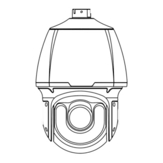
Page 10: Appearance Description
Appearance Description Dimensions Dimensions of network dome cameras are as follows. For the actual appearance, see the product. Table 1-1 Dimensions Model Dimensions IR PTZ Dome (for 46mm (1.81”) long range illumination) Smart IR PTZ Dome 193mm (7.60”) ... -
Page 11: Cable Connection
Model Dimensions 46mm (1.81”) 193mm (7.60”) IR PTZ Dome (for short 359.4mm (14.15”) range illumination) 227mm (8.94”) Cable Connection All cables are tagged to indicate their functions separately. The cables available may vary with the product model. The following takes full cable as an example. - Page 12 Figure 1-1 Cable Connection Display device Audio input Alarm output (Sound pickup) (Alarm indicator) 6 7 8 Third-party device Alarm input (Voice connected through Ground activated switch) RS485 interface Power adapter Audio output Network access (Outdoor Network access device connected sound box) device connected through optical...
-
Page 13: Mount Your Camera
Interface Function Serial port. Interact and control an external RS485 device. For example, it can control a third-party device. ALARM OUT Alarm output interface. Output alarm signals. NOTE! For the latest specifications, see the product datasheet. Mount Your Camera The following figures are for your reference only. See the actual product for details. -
Page 14: Cable Requirements
Figure 2-1 Camera Structure 1: Tail cable 2: Bracket adapter 3: Safety wire 4: Dome Verify the bearing capacity of the mounted position Verify that the mounted position meets the bearing requirements. Otherwise, you are advised to reinforce the mounted position for the device weight. - Page 15 Optical fiber The optical module in the camera should match that of the third-party device (such as a switch), in terms of fiber mode and emission/receiver wavelength. Ensure the transmission distance of the optical module is greater than the distance actually required. NOTE! For a dome camera with optical module, it should be connected to the single mode optical fiber instead of multimode optical fiber.
- Page 16 Select a high-quality fiber connector. If a non-standard fiber connector without chamfering is used, internal ceramic sleeves such as the optical module, fiber optic adapter, or optical splitter could be damaged. Ensure that the fiber connector is in good condition, the latch is ...
- Page 17 To connect a fiber connector and a fiber optic adapter, align the fiber connector with the slot in the fiber optic adapter to ensure proper interconnection. Power cable NOTE! Data listed in Table 2-1 is applicable to power cables that use 24 VAC /24 VDC power supply.
-
Page 18: Process Map
Core Diameter (Unit: mm) Distance 0.80 1.00 1.25 2.00 (Unit: m) Power (Unit: W) Table 2-2 Phoenix Connector Description Power Supply Cable Color The anode and the cathode are IR PTZ dome (for long range not distinguished for phoenix illumination)/smart IR PTZ connectors of red and black dome/laser PTZ... - Page 19 NOTE! Accessories such as the wall mount bracket and the pendant mount bracket may be necessary during installation. For supported models, refer to the accessory list recommended by your dealer. The wall bearing capacity and the bracket length must satisfy onsite ...
-
Page 20: Hardware Installation
Hardware Installation Insert the Micro SD Card (Optional) To use the local storage function, you need to install a Micro SD card. The Micro SD card is installed inside the camera. Do not hot plug the Micro SD card after it is inserted. Otherwise the camera or the SD card might be damaged. -
Page 21: Mount The Sfp Optical Module
Table 2-1 Micro SD Card Slot Description Model Micro SD Slot WDR IR PTZ Dome Slot 1 Smart IR PTZ Dome Laser PTZ Dome Slot 2 IR PTZ Dome Starlight White Light PTZ Dome Slot 3 Starlight Full Spectrum PTZ Dome... - Page 22 Turn over the tail cable adapter unit, and remove the dustproof lid. Dustproof lid Insert the SFP optical module recommended by your dealer. Connect the optical fiber plug to the SFP module, and then replace the tail cable adapter unit.
-
Page 23: Mount The Camera
Mount the Camera Wall Mount NOTE! When mounting the camera, please install the bracket adapter to the bracket first and then mount the camera to the bracket. Tighten all the screws to hold the dome securely. For waterproofing, apply sealant between the dome and the ... - Page 24 Knock in the expansion bolts and ensure that they are locked into place. Turn the bracket adapter (G1 ½ male thread) in. Bracket adapter Secure the bracket adapter with a screw.
- Page 25 Attach the safety wire to the bracket and the dome. And Lead the tail cable through the bracket. Attach the dome to the bracket adapter. Bracket adapter screw Inner track Camera holder Slide camera holders into inner track and turn camera till it is blocked by bracket adapter screw Secure the dome with two M5 screws.
- Page 26 Connect the cables and attach the bracket to the wall with flat pads, washers and nuts. Pendant Mount NOTE! The pendant mount bracket is for indoor installation only. For specially required outdoor installation, please make sure all waterproof requirements are met. We will not assume any responsibility for damage or loss incurred otherwise.
- Page 27 Locate the positions of the holes. Mark the positions of the holes by referring to the mount points of the bracket. Lead the cable through the hole on the wall. Select a drill bit matching the outer diameter of the expansion bolt.
-
Page 28: Start The Camera
Screw-in the bracket adapter (G1 ½ male thread) to the connector of the pendant mount bracket. Tighten the screws (M4) at the bracket. Mount the dome and connect all the tail cables (see step 6, 7, Wall Mount). Start the Camera After you have mounted the camera properly, connect the camera to power. -
Page 29: Reset The Camera To Default Settings
NOTE! The self-test process starts after the camera is powered up. Please wait patiently. When the operation temperature is lower than zero degree Celsius, the camera will be automatically pre-heated (the pre-heat process takes 30 minutes at most). The self-test starts only after the temperature rises above zero degree Celsius. -
Page 30: Waterproof Measures
Waterproof Measures Waterproof Components for an RJ45 Plug Attach the seal ring to the copper interface. Seal ring Mount the waterproof components. You can crimp the inner wires of the cable with the RJ45 plug first and then cover the waterproof components. You may also cover the waterproof components first. -
Page 31: Waterproof Tail Cable
Insert the cable into the Ethernet interface and screw the waterproof bolt in. Screw in the waterproof bolt lid. Bolt lid Finish the waterproof installation. Waterproof Tail Cable Connect the tail cables and then take the following steps to protect the tail cables from water using waterproof tapes. - Page 32 Connect the tail cables. Protect the connected cables using insulating tapes. Protect other cables using insulating tapes.
- Page 33 Wrap all the tail cables together using insulating tapes. Choose a start point for waterproof tapes. Waterproof tape Protect the tail cables using waterproof tapes.
-
Page 34: Set Your Camera Over The Lan
CAUTION! Avoid short circuit when insulating the cables. Use self adhesive waterproof tapes that will stick together with the twisted cables. Tighten waterproof tapes when wrapping the cables and make sure the cable connections are fully covered. You are recommended to put the waterproof cables in a waterproof ... -
Page 35: Access Your Camera
NOTE! The default IP address is “192.168.0.13”. The default username is “admin”, and the default password is “123456”. To access your camera from a different subnet, set the gateway for your camera after you log in. Access Your Camera For an IP camera, you can directly control and manage it through the web interface on a PC. -
Page 36: Install The Activex
Your camera is operating properly and connected to the network. The PC client you are using is installed with Internet Explorer 8.0 or later. Follow these steps to access your camera through the Web interface: Open your browser, input the IP address of your camera (default IP is 192.168.0.13) in the address bar and then press Enter to open the login page. -
Page 37: Adjust The Display
NOTE! For your first login with Windows 7, if the system does not prompt you to install ActiveX, follow these steps to turn off UAC: click the Start button, and then click Control Panel. In the search box, type uac, and then click Change User Account Control Settings. - Page 38 BOM: 3101C0BX...
Need help?
Do you have a question about the 6200 Series and is the answer not in the manual?
Questions and answers