Table of Contents
Advertisement
Warnings and Installation . . . . . . . . . . . . . . . . . . . . . . . . 4
Introduction . . . . . . . . . . . . . . . . . . . . . . . . . . . . . . . . . . . 5
Front Panel. . . . . . . . . . . . . . . . . . . . . . . . . . . . . . . . . . . . 6
Rear Panel . . . . . . . . . . . . . . . . . . . . . . . . . . . . . . . . . . . . 8
Signal Processing . . . . . . . . . . . . . . . . . . . . . . . . . . . . . 10
Getting Started . . . . . . . . . . . . . . . . . . . . . . . . . . . . . . . 11
Before starting . . . . . . . . . . . . . . . . . . . . . . . . . . . . . . . . . . . . . . 11
The Basic Principles of Navigation and Editing . . . . . . . . . . . . . 11
Configuration of the System. . . . . . . . . . . . . . . . . . . . . . . . . . . . 12
Adjusting the input signal . . . . . . . . . . . . . . . . . . . . . . . . . . . . . 13
First Setup . . . . . . . . . . . . . . . . . . . . . . . . . . . . . . . . . . . . . . . . 14
Display information in default conditions . . . . . . . . . . . . . . . . . . 15
System configuration . . . . . . . . . . . . . . . . . . . . . . . . . . . . . . . . . . . . 15
Number of PRESETS . . . . . . . . . . . . . . . . . . . . . . . . . . . . . . . . . . . 16
Type of PRESET . . . . . . . . . . . . . . . . . . . . . . . . . . . . . . . . . . . . . . 16
Name of the PRESET . . . . . . . . . . . . . . . . . . . . . . . . . . . . . . . . . . 16
PRESET Modifications . . . . . . . . . . . . . . . . . . . . . . . . . . . . . . . . . 17
System Protection . . . . . . . . . . . . . . . . . . . . . . . . . . . . . . . . . . . . . . 17
Menu map. . . . . . . . . . . . . . . . . . . . . . . . . . . . . . . . . . . . 18
Menu map . . . . . . . . . . . . . . . . . . . . . . . . . . . . . . . . . . . . . . . . . 18
Variations of the Audio Parameter editing pages . . . . . . . . . . . . 20
PRESET menu . . . . . . . . . . . . . . . . . . . . . . . . . . . . . . . . 22
Load PRESET . . . . . . . . . . . . . . . . . . . . . . . . . . . . . . . . . . . . . . 23
Store & Naming PRESET . . . . . . . . . . . . . . . . . . . . . . . . . . . . . 24
Dump Out PRESET . . . . . . . . . . . . . . . . . . . . . . . . . . . . . . . . . . 25
Incoming Dump . . . . . . . . . . . . . . . . . . . . . . . . . . . . . . . . . . . . . 25
Contents
Contents
1
Advertisement
Table of Contents

Related Manuals for LEM DX 26 PLUS


Summary of Contents for LEM DX 26 PLUS
-
Page 1: Table Of Contents
Contents Contents Warnings and Installation ......4 Introduction ........5 Front Panel. - Page 2 Contents DELAY Menu ....... . . 26 The practical differences between Input and Output Delay ..26 Input Delay .
- Page 3 Contents Input Select ......... . . 44 Output Meters .
-
Page 4: Warnings And Installation
In the event of breakdown All user-adjustable parts are external and easily accessed. In the event of a breakdown, do not open the apparatus, but contact the nearest Generalmusic/Lem Service Centre. Keeping the documentation Keep this user’s manual for future consultation. Also remember that the effect will get a better price on the... -
Page 5: Introduction
All operations are carried out via user interface that includes a 2x16 LCD, a convenient DIAL for the parameter modification and selector buttons for the direct access to all the features. DX 26 PLUS is also equipped with 2 types of serial interface (RS232 and RS485) for the remote control thru a PC and... -
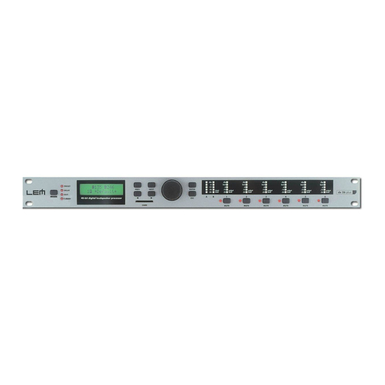
Page 6: Front Panel
Front Panel Front Panel MODE Key for selecting the PRESET, DELAY, EDIT and UTILITY menus. Selection is made by pressing MODE repeatedly until the required menu is reached, indicated by the relative LED. Selecting a menu allows access to the editing of its parameters. If none of the menu LEDs are lit, the display shows the name of the current PRESET (i.e. - Page 7 Holds a MULTIMEDIA CARD on which 128 User PRESETS can be stored and recalled whenever required. MEMORY CARDS are very useful for safe storage for later use of PRESETS and for their transfer from one DX 26 PLUS to another one. INPUT LEVEL A-B LED ladders indicating the level of inputs A and B.
-
Page 8: Rear Panel
PLUS units. Communication protocol includes: - Remote control: connecting the DX 26 PLUS to a PC and using the LEM editing software is possible to remotely control all the processor functions. - PRESET DUMP: connecting two DX 26 PLUS it’s possible to DUMP the single PRESETS from one unit to the other (see DUMP procedure). - Page 9 RS485 IN & OUT RS485 standard serial communication interface port. Allows incoming and outgoing communication between a DX 26 PLUS and a PC or other DX 26 PLUS units. The characteristics of the RS485 interface make these ports particularly suitable for remote control over long distances (difficult with RS232 standard ports) and for daisy-chaining several DX 26 PLUS.
-
Page 10: Signal Processing
Signal Processing Signal Processing Balanced inputs (IN A & IN B). 20-bit A/D converters. LED ladders for monitoring input signals. NOISE GATE on the inputs. 5-band parametric equalizers for A & B inputs. 3 delay lines (IN A, IN B & Sum A+B). Routing System for connecting INPUTS and OUTPUTS. -
Page 11: Getting Started
So before going ahead, it’s advisable to get to know at least the introductory part of this manual. The Basic Principles of Navigation and Editing All the DX 26 PLUS parameters and functions can be accessed and edited using the buttons on the front panel. All available information is shown on each occasion on the display. -
Page 12: Configuration Of The System
Refer to the Connections chapter and, with the equipment switched off, carry out the audio and power connections among the various components of your sound system. Connect the mains cable and switch on only the DX 26 PLUS. The display shows data regarding the operating system release for a few seconds. -
Page 13: Adjusting The Input Signal
(high level square wave). Proceed as follows: + Keep the DX 26 PLUS outputs in MUTE status (LEDs lit). + Feed a signal in on the DX 26’s input and watch the INPUT LEVEL A-B LED ladders. -
Page 14: First Setup
Getting Started First Setup At this point, the first custom setup can be prepared. The following is only a description of setup procedure. The detailed specifications of each parameter are shown in the respective paragraphs of the manual. Firstly, set the following parameters in the order shown: Output Pol. -
Page 15: Display Information In Default Conditions
Getting Started Display information in default conditions In default conditions, i.e. when none of the menu LED’s is lit, so no type of editing is enabled, the display shows the main information on the PRESET currently stored in the memory: A 1 3 B 2 4 S 5 6 2 x 2 W + 2 M A X There are various information areas:... -
Page 16: Number Of Presets
N.B.: the name of a Factory PRESET normally indicates the general structure of the sound system to be connected to the DX 26 PLUS or of a specific speaker enclosure model. The name of a User PRESET and a Card PRESET can be edited as required. For example:... -
Page 17: Preset Modifications
Getting Started PRESET Modifications M A 1 3 B 2 4 S 5 6 PRESET Modifications 2 x 2 W + 2 M A X This indication shows that the value of one or more parameters has been temporarily modified with respect to the values stored in the PRESET shown. -
Page 18: Menu Map
Menu map Menu map Menu map The control software is organized in PRESET, DELAY, EDIT and UTILITY menus, each of which contains the relative types of parameters and functions. To facilitate menu navigation, refer to the following map: menu Load Preset PRESET Store Preset Dump Out Preset... - Page 19 Menu map menu Ganging Input Ganging UTILITY Output Ganging Units Delay Unit Lim. Thresh. Unit Temperature Unit Misc. Setup Input Select Output Meters Temperature Wake Up LCD Contrast Lock Lock Memory Card Format Card Comm. Setup Preset Change RX...
-
Page 20: Variations Of The Audio Parameter Editing Pages
Variations of the Audio Parameter editing pages parameters DX 26 PLUS can be configured with a large number of IN/OUT combinations. In some configurations certain parameters aren’t used. To streamline editing, the system only presents the parameters that can be used on each occasion. - Page 21 Menu map This also affects the number and contents of the editing pages on each occasion. For example, the INPUT DELAY editing pages can have the following variations: DX 26 PLUS - INPUT DELAY EDITING PAGES INPUT CONFIGURATION PAGES PARAMETERS...
-
Page 22: Preset Menu
PRESET menu PRESET menu This menu allows access to the Presets’ control: menu Load Preset PRESET Store Preset Dump Out Preset Incoming Dump There are 3 distinct categories of PRESETS: Factory PRESETS Factory-programmed storage. Factory PRESETS can be used normally, temporarily modified, but can’t be cancelled, overwritten or permanently modified. -
Page 23: Load Preset
Loading a PRESET, a PRESET Change command is also automatically sent to the serial ports and can be used to automatically load a PRESET with the same number to any other DX 26 PLUS units con- nected and enabled (see UTILITY menu - Comm. Setup submenu - PRESET Change RX option). -
Page 24: Store & Naming Preset
PRESET menu Store & Naming PRESET This menu page allows to create new PRESETS, i.e. to save all the current system settings. S t o r e P r e s e t 2 x 2 W + 2 M A X To save a PRESET: Use DIAL to reach the memory area in which the PRESET is to be saved. -
Page 25: Dump Out Preset
Dump Out PRESET This menu page allows to download a PRESET via the serial ports. This allows to immediately “copy” the settings of the various PRESETS of a DX 26 PLUS to another DX 26 PLUS. D u m p O u t P r e s e t... -
Page 26: Delay Menu
DELAY Menu DELAY Menu This menu allows to work on the system’s delay lines. menu Input Delay parameters DELAY Output Delay parameters parameters In these pages, the number of the parameters and how they are presented varies according to the configuration of the PRESET and according to Ganging and Units settings (UTILITY menu). In fact, these pages only show the parameters that can actually be used, in the most suitable form of editing. -
Page 27: Input Delay
DELAY Menu Input Delay This menu page allows to adjust the delay lines of Input A, Input B and SUM. I n p u t D e l a y The values can be set in the following ranges: INPUT DELAY I N A D E L A Y 7 7 m s... -
Page 28: Output Delay
DELAY Menu Output Delay This menu page allows to adjust the delay lines of outputs 1, 2, 3, 4, 5 and 6. O u t p u t D e l a y The values can be set in the following ranges: OUTPUT DELAY O P 1 D E L A Y... -
Page 29: Edit Menu
EDIT menu EDIT menu This menu allows to edit the system’s actual audio parameters. menu Input Gain parameters EDIT Noise Gate parameters Input EQ parameters Input GATE parameters Xover parameters Output EQ parameters Output Gain parameters Output Pol. parameters Output Cmp/Limit parameters parameters In these pages, the number of the parameters and how they are presented varies according... -
Page 30: Input Noise Gate
EDIT menu Input Noise Gate Noise reduction filter onthe inputs. Aloows to cut or reduce the background noise generated by the unit connected to the processor’s inputs (the mixer, for example). The filter is active when the input signal is below a certain threshold and reduce its level cutting the undesired background noises. -
Page 31: Input Eq
EDIT menu Input EQ Input equalizer with 5 parametric filters. Allows to alter the overall tone of the signal connected to the respective input. Also called Master EQ, the equalization of the input signal effects all the outputs connected to the input and the input SUM. -
Page 32: Type Of Filter
EDIT menu The following editable parameters are available for each filter: Type of filter Allows to choose among Peaking, Low or High Shelving with a slope of 6 or 12 dB per octave and Notch filter. I N A E Q 1 P e a k 2 k 0 0 1 . -
Page 33: Gain
EDIT menu Gain Allows to control the boost or cut of the selected frequencies. It’s not used with the Notch Filter, which has a fixed cut. I N A E Q 1 P e a k 2 k 0 0 1 . 0 - 5 . -
Page 34: Xover
EDIT menu Xover Low-pass and high-pass filters. Made up of a combination of a low-pass filter and high-pass filter, the crossover allows to divide the audio signal into segments that can be used by the individual sections of a sound system (for example High, Mid &... -
Page 35: Type Of Filter
EDIT menu Each filter has the following editable parameters: Type of filter Allows to choose three different types of filter and different attenuation slopes: Butterworth (But) at 6, 12, 18 or 24dB per octave, Bessel (Bes) at 12, 18 or 24dB per octave, Linkwitz-Riley (LR) a 12, 24 or 48dB per octave. -
Page 36: Output Eq
EDIT menu Output EQ Output equalizer with 5 parametric filters. Also called Channel EQ, allows to alter the tone of each individual output. The characteristics of quality and programmability are identical to those of the Input Equalizer and enable this unit to be used extremely effectively and flexibly. O u t p u t E Q Each equalizer has 5 pages (one per filter), indicating the name of the output it effects and the num- ber of the filter. -
Page 37: Output Gain
EDIT menu Output Gain Output level control. Allows to adjust the signal level of each individual output. O u t p u t G a i n Editing values are between +6dB ÷ -30dB, with 0.5dB steps. O P 1 G A I N - 6 . -
Page 38: Output Compressor/Limiter
EDIT menu Output Compressor/Limiter Output level compressor/limiter. Allows to keep the signal of each individual output within a set level. Can be used effectively to protect the components of a sound system or to obtain compression effects and to increase the signal dynamics while keeping it within certain limits. O u t p u t C o m p L i m The following editable parameters are available:... -
Page 39: Ratio
EDIT menu Ratio Allows to set the compression ratio, that is to say how the signal exceeding the trheshold has to be reduced. The editing values are the following: Lim. 20.0 10.0 8.0 6.0 5.0 4.0 3.5 3.0 2.5 2.0 1.7 1.5 1.3 1.1 O P 1 C o m p L i m O P 1... -
Page 40: Utility Menu
UTILITY menu UTILITY Menu This menu comprises a series of submenus that allow to set a series of system options and access certain utilities, such as the control of the Multimedia Memory CARD or protection against accidental or unauthorized changes: menu Ganging Input Ganging... -
Page 41: Ganging Submenu
UTILITY menu ANGING SUBMENU Ganging Input Ganging Output Ganging This submenu allows to group together the treatment of similar inputs and/or outputs. Similar is intended as meaning elements which have the same properties and/or the same structure. For example, the right and left sections of a stereo system are similar, as they are made up symmetrically of the same quantity and type of elements (the same components for High, Mid and Low frequencies). -
Page 42: Input Ganging
UTILITY menu So generally speaking, to avoid contradictions, oversights and confusion between what is shown and what is effectively carried out, it’s advisable to enable the Ganging functions before starting to edit a PRESET. Moreover, it’s best to make certain to effectively set the required value, manually confirming all the parameters required. N.B.: the elements in Ganging assume the “new”... -
Page 43: Units Submenu
UTILITY menu NITS SUBMENU Units Delay Unit Lim. Thresh. Unit Temperature Unit This submenu allows to choose the measurement units to be used with certain functions. U n i t s Delay Unit Allows to set the measurement units in which Delays are expressed (DELAY menu). The options include: m = meters - mm = millimeters - ms = milliseconds - ms = microseconds Measurement units for Input Delay Measurement units for Output Delay... -
Page 44: Misc. Setup Submenu
LCD Contrast This submenu allows to set a series of system options. M i s c . S e t u p Input Select Allows to choose which DX 26 PLUS inputs to use. The options include: Digital Inputs Analog Inputs... -
Page 45: Output Meters
UTILITY menu Output Meters Allows to decide whether to display the outputs’ signal before or after MUTE. The options include: PreMute PostMute the signal is always shown the signal is only shown if no matter what the MUTE status the output isn’t in MUTE O u t p u t M e t e r s O u t p u t M e t e r s P r e M u t e... -
Page 46: Wake Up
UTILITY menu Wake Up Allows to choose the mode in which MUTE functions are restored when the DX 26 PLUS is switched on. The options include: Normal Mute when switched on, the system restores the last when switched on, the system automatically... -
Page 47: Lock Submenu
UTILITY menu OCK SUBMENU Lock Lock Allows to enable or disable the protection of the system against accidental or unauthorized changes. L o c k This function is very useful whenever even temporary changes or tampering with the settings stored in the system must be prevented. -
Page 48: How To Disable The Protection
UTILITY menu How to disable the protection If the protection is enabled, when the system is in default status (i.e. when none menu LEDs are lit and therefore no type of editing is enabled), the following appears on the display: Total Protection enabled Partial Protection enabled A 1 3 B 2 4 S 5 6... -
Page 49: Memory Card Submenu
UTILITY menu EMORY ARD SUBMENU Memory Card Format Card Allows to format the Multimedia Memory Card. Formatting is the preparation of the memory areas of the Card. Without formatting (or without compatible formatting) the Card can’t be used by the system. M e m o r y C a r d How to format the Card ☞... -
Page 50: Comm. Setup Submenu
PRESET with the corresponding number. This means that, in a chain of DX 26 PLUS, all the units set with “PRESET Change RX = Accept” load the same number of PRESET, in spite of the fact that it corresponds to PRESETS with different contents in the various units. -
Page 51: Configurations
Configurations Configurations The following diagrams show the DX 26’s various system configurations, as if to say the various input and output hardware combinations. - Page 52 Configurations...
- Page 53 Configurations...
-
Page 54: Connections
Connections Connections The following diagrams show the schemes of the recommended cables and some connection examples referred to various system configurations. Inputs A & B, Digital IN, RS485 IN BALANCED XLR-M Inputs A & B BALANCED JACK Outputs 1÷6, RS485 OUT BALANCED XLR-F RS232 RS232 (9-Pin) - Page 55 Connections...
- Page 56 Connections...
- Page 57 Connections...
- Page 58 Connections...
- Page 59 Connections Communications: PC & one or more DX 26 PLUS connection...
- Page 60 Connections Communications: two DX 26 PLUS short distance connection Communications: two or more DX 26 PLUS long distance connection...
-
Page 61: Factory Presets
PFC5 (1500W/4ohm) IMPORTANT NOTE The OUTPUT LEVEL and LIMITER THRESHOLD settings of the FACTORY PRESETS for LEM enclosures have been made considering the OUTPUT POWER and INPUT SENSITIVITY specifications of the LEM POWERFACTOR amplifiers in the CONSTANT GAIN (26dB) configuration. -
Page 62: Technical Specifications
Technical Specifications Technical Specifications INPUT section Connectors 2 x COMBO Nominal input sensitivity 0 dB (0.775 V) Input Impedance 30kOhm, electronically balanced Maximum Input Level +20dBu Input Gain -30 / +6 dB variable in 0.5 dB steps Digital input AES/EBU, XLR-F Digital input sample rate 32 kHz ÷... - Page 63 FEDERAL COMMUNICATIONS COMMISSION NOTE: This equipment has been tested and found to comply with the limits for a Class A digital device, pursuant to Part 15 of FCC Rules. These limits are designed to provide reasonable protection against harmful interference when the equipment is operated in a commercial environment.
Need help?
Do you have a question about the DX 26 PLUS and is the answer not in the manual?
Questions and answers