Table of Contents
Advertisement
Advertisement
Table of Contents

Summary of Contents for Ukcutter SMURF HW1200
- Page 1 OPERATOR'S MANUAL...
-
Page 2: Table Of Contents
Table of Contents 1. Safety precautions............2 1.1 Safe using methods............2 1.2 Definition of warning symbols..........2 2. Standard accessories............5 3. Product Structure Diagram............6 4. Installation & Setup..........6 a. Floor stand............6 b. Installation and use............7 c. Power connection............7 d. Serial RS232 cable and USB cable connection.......7 e.1 USB Printer Mode ..............8 e.1.i Software Setup Guide for USB Printer Mode …....8 e.2 Virtual COM USB..............8... -
Page 3: Safety Precautions
1. Safety precautions Please follow the instructions with the signs below, to ensure correct use of the vinyl cutter and prevent damage. 1.1 Safe using methods WARNING Improper operation can possibly result in a life hazard or damage of equipment. CAUTION Improper operation can possibly result in a life... - Page 4 CAUTION Don’t pour liquid or drop metal into the machine, they can cause fire. Don’t touch the knife top with your finger to prevent injury or perspiration of knife head. Do not damage or replace the supplied power cable. Do not (excessively) bend, pull, bundle the power cable or place weight on it.
-
Page 5: Standard Accessories
2. Standard accessories The following accessories should be included in the package, please contact the seller if anything is missing. Part Picture Power cable USB cable RS232 cable Blade holder Blade Warranty Card Driver CD 3. Product Structure Diagram... -
Page 6: Installation & Setup
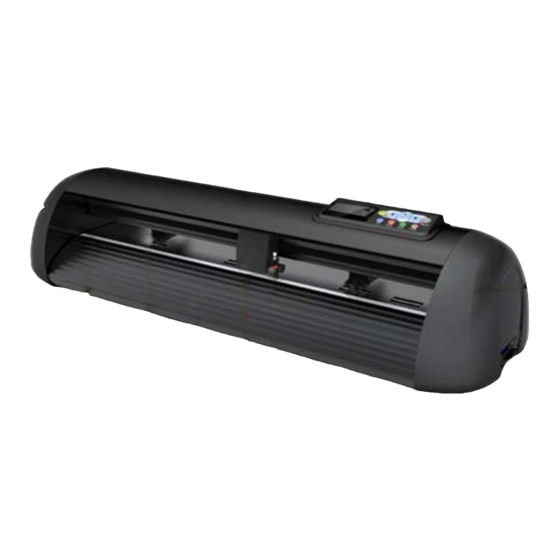
1. Platform 2. Cover 3. Control Panel 4. Carriage 5. Blade holder 6. Pinch roller group 7. Trim strip 8. Upper cover plate 9. Power socket and switch 10. RS232 serial port, USB port, SD interface 4. Installation & Setup a. -
Page 7: Power Connection
— A place that is unstable — A dusty place — A place where temperature or humidity can vary significantly c. Power connection Check the voltage of the electrical connection and power supply before you connect the cutter’s cable. d. Serial RS232 and USB cable connection Connection options (plug only one at a time) Note: You only need to use either a RS232 serial cable or a USB cable for connecting your computer with the cutter (unlike above pictures where both are connected for illustration purposes). -
Page 8: E.1.I Software Setup Guide For Usb Printer Mode
Software Setup Guide for USB Printer Mode e.1.i 1. Choose "Vicsign" as the Manufacturer 2. Choose "HW330" as the Cutter 3. Link to "USB001" 1. Click "Cutter" to open the cutter settings dialogue 2. Choose "Vicsign" as the Manufacturer, and choose "HW330" as the Cutter model 3. - Page 9 1. Select the objects you wish to Cut, and click the Cut Tool plugin from the drop-down menu. Be sure to select the version which matches your version of CorelDRAW ... 2. Now click "Cut/Plot" and Select "USB001" as the Port. 3.
- Page 10 Contour Cutting from CorelDRAW 1. Select the objects you wish to Cut, and click the Cut Tool plugin from the drop-down menu. Be sure to select the version which matches your version of CorelDRAW ... 2. Set the Outside Offset amount, and then click "Trace Contour" Note: IF THERE ARE NO LINES IN THE OUTPUT PREVIEW THEN PLEASE MAKE SURE THE DESIGN IS VECTOR/PATHS/CURVES.
-
Page 11: Rs232 Serial Com
Note: If the Contour position is offset then please follow our video guide on how to calibrate the ARMS. The video can be found on the Disc that came with your SMURF cutter, or online here: http://download.ukcutter.co.uk/videos/cutters/SMURF_calibration.mp4 e.3 RS232 Serial... -
Page 12: Sd Card (Secure Digital Memory Card)
RTS / CTS (only selected third) Command Set: Initialization :: H A LO EC1 U Carrying knives go U Delimiter, At the end, Homing @ Page End U F Knife pressure Knife speed f. SD Card (Secure Digital Memory Card) Make sure the SD Card is formatted as FAT16/FAT32 with NO directories/folders. - Page 13 Note: Files can be sent as PLT in Artcut and CorelDraw software. 2. Insert SD card into the cutter, press "Origin”, and use the UP▲ and DOWN▼ arrow keys to find your file. Press "Enter” to load your selected file.
-
Page 14: Media Installation
Note: When removing the SD card from the cutter, please do not extract directly. Tap the SD card with your finger and it will pop out. g. Media installation 1. Media storage and use precautions — After opening the package, store the media in a cool dark place to avoid contact with sunlight and water —... -
Page 15: Knife Setting And Adjusting
Depress the lever of pinch roller Insert the media correctly. Move the roller to cover the steel shaft claw, it can ensure the best tracking length when you allow the media away from the machine both at left and right side. Handle the stage, and press the media. -
Page 16: Drawing Pen Installation
3. Install the blade holder into the carriage — Loosen the screw of the tool carrier — Assemble the blade holder into the tool carrier — When the tool is in appropriate position, tighten the screw. i. Drawing pen installation The installation method for the pen is basically the same as with the blade holder, except for adjusting the nib. -
Page 17: Media And Carriage Positioning
Offline state c. Media and carriage positioning When the plotter is offline, press the LEFT ◄ or RIGHT ► arrow keys to move the carriage left or right. Press the UP ▲ and DOWN▼ arrow keys to move the media feed roller forward / backward. -
Page 18: Setting The Origin
f. Setting the origin You can set the absolute origin of the media to the lower right corner, or any other position, by using the up/down and left/right keys to move to the preferred position. Then press “Origin” to clear the current coordinates and set the current position as the new origin for cutting. - Page 19 Click next, Select “I agree the terms of the license agreement”, and click “Next”. Select the installation path, click “Next”.
-
Page 20: Flexi Operation
Now please connect the dongle to the computer, input your password and it will automatically show your User Number ID, as shown below. Select Language, and click “Done” to complete the installation (a desktop shortcut will automatically be created). a. Flexi operation 1. - Page 21 2. The software will automatically open the "Add Setup" dialog box. Select brand name and model name accordingly, and click “Next”, as below: 3. Select connection method...
- Page 22 Caution: please check and make sure the Flexi interface port is the same as shown in Device Manager, otherwise the cutter will not work. Those two ports should be the same 4. Please choose the same port as the cutter output port, the other parameter is the same as handshare agreement (above picture) show, baud rate: 38400, hardware handshake agreement “RTS”...
-
Page 23: Automatic Cruise Edge (Optional)
b. Automatic cruise edge (optional) 1. Open Flexi software, import the graphic file and click on the blank part of the image. The software will auto switch to “design centre” dialog, where you can set the cutting material size; for example, if you need to cut in A4 size material, set the size to “A4” as the picture shows below. - Page 24 Then click “effect” in menu, click “Contour Cut Mark”, SA automatically mark after cutting accuracy is the most accurate, as the picture show:...
- Page 25 5. Print ready files. Note: the print scale is 100% 6. Send the printed graphic to the cutter, the image needs to be put straight. 7. While Offline, move the blade to the red dot as the following picture shows, and press “Origin”...
- Page 26 Click “cut contour” and send 8. FLEXI software will automatically pop-up the dialog below. Select the cutter brand name ”Vicsign”, and the model name/number.
- Page 27 9. Click “Next”. Please note: if you use a USB port connection, please open the computer’s “Device Manager” to check if the port selected in Flexi is the same as the port for the installed driver. If it is not the same, the cutter will not work. These two ports should be the same...
Need help?
Do you have a question about the SMURF HW1200 and is the answer not in the manual?
Questions and answers