Table of Contents
Advertisement
In the interests of user-safety (Required by safety regulations in some countries) the set should be restored
to its original condition and only parts identical to those specified should be used.
¨
Multi 21 System, 100-CH Program Memory
¨
Full Auto Search System
¨
NTSC Colour Comb Filter
¨
CATV (Hyperband) Ready
¨
NTSC Colour Comb Filter Function
¨
High Contrast Picture (Black Strecth Circuit)
¨
White Temperature Select
¨
English Language OSD
¨
Specifications ............................................. 2
¨
IMPORTANT SERVICE NOTES ........................ 2
¨
Adjustment Precautions ........................ 3
¨
TROUBLE SHOOTING TABLE ....................... 16
¨
WAVEFORMS .................................................. 18
¨
Solid State Device Base Diagram ....... 19
¨
¨
DIAGRAM:
¨DIAGRAM BLOCK CRT ............................. 21
¨DIAGRAM SCHEMATIC CRT ..................... 22
The chassis in this receiver is partially hot. Use an isolation transformer between the line cord plug and power
receptacle, when servicing this chassis. To prevent electric shock, do not remove cover. No user - serviceable parts
inside. Refer servicing to qualified service personnel.
SERVICE MANUAL
FEATURES
CONTENTS
Page
WARNING
SHARP CORPORATION
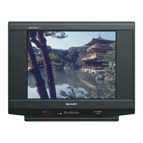
COLOUR TELEVISION
Chassis No. GA-8S
MODEL :
21ES251E
21ES253E
21ES353E
¨
Blueback Function Noise Mute
¨
OFF Timer & Child Lock
¨
Hotel Mode & AV Mode (Movie/Music/News)
¨
Surround Sound Effect
¨
Rear AV-IN Terminal
¨
Rear AV-OUT Terminal
¨
Save Mode
¨
AV Stereo & Equalizer
¨ MAIN BLOCK
........................................... 23
¨ MAIN SCHEMATIC ................................... 24
¨
REPLACEMENT PARTS LIST
1
Page
Advertisement
Table of Contents

Summary of Contents for Sharp 21ES251E
-
Page 1: Service Manual
SERVICE MANUAL COLOUR TELEVISION Chassis No. GA-8S MODEL : 21ES251E 21ES253E 21ES353E In the interests of user-safety (Required by safety regulations in some countries) the set should be restored to its original condition and only parts identical to those specified should be used. - Page 10 H-VCO, VIF-VCO & S-TRAP fo ADJUSTMENT ADJUSTMENT CONDITION / PROCEDURE WAVEFORM OR OTHERS ADJUSTMENT POINT 1 H-VCO ADJ (Manual Adj) (I2C BUS CONTROL) (1) In No signal (RASTER) condition. (2) Go to service mode, choose service data V03. (AUTO & MANUAL ADJ) (3) Connect oscilloscope to IC801 pin13 (H-OUT), adj V03 until freq become 15.625 ±...
- Page 11 HORIZONTAL ,VERTICAL,DEFLECTION LOOP ADJUSTMENT (2) ADJUSTMENT CONDITION / PROCEDURE WAVEFORM OR OTHERS ADJUSTMENT POINT UPPER CORNER (1) Receive CrossHatch Pattern Signal (PAL 50 Hz). (I2C BUS CONTROL) (2) Choose the service data V38 (3) Adjust the 2nd upper vertical line from the right end of the crosshatch pattern so that the upper line are straight.
- Page 18 WAVE FORM (1)1.78 Vp-p (2)4.80 Vp-p (3)3.84 Vp-p (4)4.76 Vp-p Horiz. Rate Horiz. Rate Horiz. Rate Horiz. Rate (5)3.16 Vp-p (6)4.66 Vp-p (7)5.60 Vp-p (8)1.57 Vp-p Horiz. Rate Vert. Rate Horiz. Rate Vert. Rate (9)2.60 Vp-p (10)20.80 Vp-p (11)1110 Vp-p (12)63.40 Vp-p Horiz.
- Page 19 21EXS350 IXC844WJ A1530 M24C16 C2735 CATHODE CATHODE CATHODE IXC844WJ CATHODE ANODE ANODE ANODE ANODE EXA520WJ EXA535WJ EXA572WJ ISS356 2SC3198-G 2SA1266 KIA78R05 STRW6553 2SC3198-Y 2SD1913 2SD468-C C6090++1 D3SB 60 74 CATHOD ANODE (RED) LA78041 PK0013 DX0470CE CATHOD ANODE DX0445CE COLLECTOR Vout SE125N++ LA42102+...
-
Page 20: Description Of Schematic Diagram
DESCRIPTION OF SCHEMATIC DIAGRAM NOTES: SAFETY NOTES: 1. The unit of resistance "ohm" is omitted. 1. DISCONNECT THE AC PLUG FROM THE AC OUTLET BEFORE (K = 1000 ohms, M = Mega ohm). REPLACING PARTS. 2. All resistors are 1/16 watt, unless otherwise noted. 2. - Page 21 21ES251E / 21ES253E / 21ES353E...
- Page 22 MARTINUS DEDI S. DIAN T. GA-8S CRT (All 21"US) 21EPS258E / 21EMS258E / 21ECS258E / 21ES251E / 21ES353E / 21ES253E KZ018JCE...
- Page 25 COPYRIGHT © 20 ALL RIGHTS RESERVED.


Need help?
Do you have a question about the 21ES251E and is the answer not in the manual?
Questions and answers