
Summary of Contents for Mavigard MG-400
- Page 1 COMMISSIONING, OPERATING AND MAINTENANCE MANUAL MG-400 MODEL: MAVIGARD SERIES SUB MODEL: CONVENTIONAL SYSTEM COMBINED GAS AND FIRE ALARM CONTROL PANEL...
-
Page 2: Table Of Contents
CONTENTS 1. INTRODUCTION ----------------------------------------------------------------------------------------------------------------------------------------------- 3 2- WARNING ------------------------------------------------------------------------------------------------------------------------------------------------------- 3 3- MOUNTING THE PANEL ------------------------------------------------------------------------------------------------------------------------------------- 3 4- PANEL INPUTS ------------------------------------------------------------------------------------------------------------------------------------------------- 4 4.1 Mains Power Supply ------------------------------------------------------------------------------------------------------------------------------------ 4 4.2 Batteries --------------------------------------------------------------------------------------------------------------------------------------------------- 4 4.3 Channel Inputs ------------------------------------------------------------------------------------------------------------------------------------------- 4 4.3.1 Fire detectors and MCPs ------------------------------------------------------------------------------------------------------------------------ 4 4.3.2 4-20mA input-------------------------------------------------------------------------------------------------------------------------------------- 4 4.3.3 Connections of 4-20mA converter card ----------------------------------------------------------------------------------------------------- 4 4.3.4 Two-wire detectors ------------------------------------------------------------------------------------------------------------------------------- 5... -
Page 3: Introduction
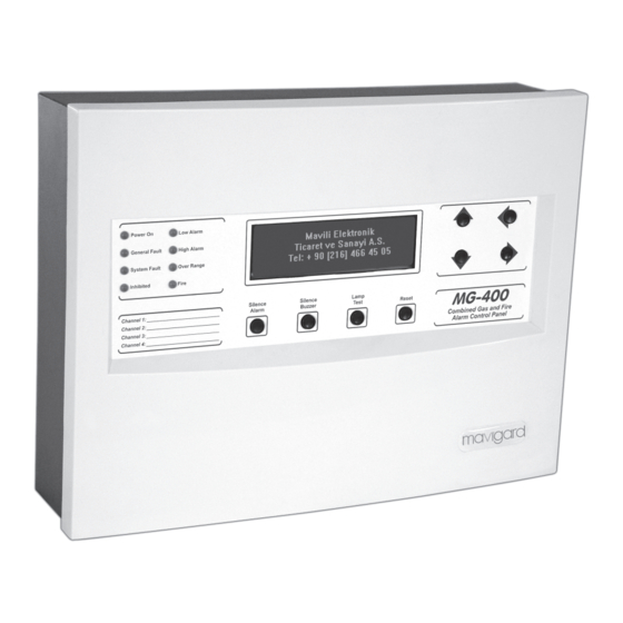
1. INTRODUCTION MaviGard MG-400 is a 4 channel, 24 V DC operating voltage combined gas and fire alarm control panel. Each channel can host 1 gas detector or 20 fire detectors with unlimited number of manual call points. Panel power supply unit has an automatic battery charger and charging control circuit. Alarm and fault conditions are showed on 8x40 character backlight LCD. -
Page 4: 4- Panel Inputs
4- PANEL INPUTS 4.1 Mains Power Supply The panel is designed to operate on 220 V AC 50Hz. Earth connections must be made to earth terminal and earth resistor must be less than 10 Ohms. The mains power supply of the panel must be via an independent self-resetting fuse rated 5A 220 V AC. -
Page 5: Two-Wire Detectors
4.3.4 Two - wire detectors In Figure-8, Annex. A ; a sink current detector’s connection is shown. Appropriate jumper settings should be selected. 4.3.5 Three - wire detectors In Figure-9 Annex-A; a 3-wire detector’s connection is shown. Appropriate jumper settings should be selected as sink or source. -
Page 6: Fault Relay
5.3.4 Fault relay: When fault condition or panel’s energy is cut off, it changes its position. When the fault condition disappears, fault relay gets back to its initial position. Important Note: Under no circumstances should voltage or current outside of 1A at 30 V DC used with contacts. -
Page 7: 8- Fuses
Over - Range Shows the gas level in the medium exceeds a fixed high limit (21.5 mA), over-range relay is activated. General Alarm Shows if there is a gas or fire alarm from the detectors connected to the channels. 8- FUSES Sounder 1 Fuse (F1) F1 fuse;... -
Page 8: 9- Powering The Panel
9- POWERING THE PANEL 9.1 Normal During normal mode, only green system is on LED lights. On the screen the gas levels read by channels is 9.2 Alarm When the gas detectors exceed the levels of predetermined threshold levels in each channel, panel goes into alarm mode. - Page 9 10.1.1 Relay Activation Status It enables to track the position of relay outputs of the panel. *** RELAYS STATUS *** Low Alarm Relay: Active High Alarm Relay: Not Active Over-range Relay: Not Active Fault Relay: Active ------------------------------------------------------------- ----- Exit – Pre Menu 10.1.2 Sounder Activation Status It follows whether sounder outputs are active or not.
- Page 10 10.1.4.1 System In this menu, panel’s language is shown. * SYSTEM * Language: English Access Level 2 Password: Active --------------------------------------------------------- ---- Exit – Pre-menu 10.1.4.2 Common relay settings It is possible to check how panel’s relay works (latching or non-latching and N/O or N/C) *COMMON RELAY SETTINGS* Low Alarm Relay : Latching / NO High Alarm Relay: Non-latching / NC...
-
Page 11: Access Level
*** CHANNELS *** Channel 1configıuration Detector measurement range : Zero forcing: 2 mA condition: Warm-up delay : ----------------------------------------------------------- Exit – Pre-menu *** CHANNELS *** Channel 1configıuration Fire Reset time : Level Alarm position : Level Alarm Entrance Value: Level Alarm End Value : ------------------------------------------------------------ Exit –... - Page 12 *** INHIBIT*** > All :Inhibition not active Channel 1 :Inhibition not active Channel 2 :Inhibition not active Channel 3 : Inhibition Active Channel 4 : Inhibition Active ------------------------------------------------------------ Enter – Ok Exit - Pre Menu Using “Up (+)” and “Down (-)” buttons channel which wants to be inhibited is selected. The sign ‘>’ on the left of the channel is moved).
- Page 13 10.2.3 Calibration In order to make the calibration of the detectors, this function is used. It composes of 3 sub-functions. *** CALIBRATION *** > Calib. Channel. Calib. Level: Calibrate ------------------------------------------------------------ Exit – Pre Menu First of all the channel which want to be calibrated is selected. To do that the sign “>” should be in the left side of the sub-function “Calib Channel”.
- Page 14 10.2.4 Test This function enable us test the relays and sounder outputs. *** TEST *** > Relay Test Sounder Test ------------------------------------------------------------ Exit-Main Menu 10.2.4.1 Relay Test In the Relay test function, the current status of the relays are monitored at the panel. *** RELAY TEST*** >...
- Page 15 10.2.5.1 System Panel: Network Address, communication rate, panel name, serial number and panel language are adjusted by the help of system menu. *** SYSTEM *** > Language: English Access Level 2 Password: Active -------------------------------------------------------------- Enter – Ok Exit – Pre Menu 10.2.5.2 Common Relay Settings In this sub-function, relays operating structure are set as latching, non-latching or latching acceptance of operating status and N/O or N/C is adjusted.
- Page 16 10.2.5.3 Sounder settings The sounder outputs of the control panel are adjusted. *** SOUNDER SETTINGS * ** > Sounder 1 : Latching Sounder 2 : Non-latching ------------------------------------------------------------ Enter – OK Exit – Pre Menu On this screen, it is possible to find the sounder output which you may want to adjust setting, using “Up(+)” and “Down(-)”arrow buttons.
- Page 17 ·By “2mA detection” function, in case of decreasing current which comes from detector or converter card, the system response is determined. In this condition system may give fault warning, notification warning or cannot be counted as a warning status. ·By “W arm-up delay” function, it is told to the control panel that, in the start –up session, the signals coming from the detectors cannot be evaluated by the panel.
-
Page 18: Operating With Repeater Panel And Relay Module
11 – OPERATING WITH REPEATER PANEL AND RELAY MODULE MG-400 Series Control Panel has appropriate connections for repeater panel and relay module for each zone output. Yet these features are not available to use currently. 12- SPECIFICATIONS: 12.1 Mechanical Features:... -
Page 19: Annex-A Connection Scheme Of The Panel
ANNEX-A CONNECTION SCHEME OF THE PANEL KK-642.014 Rev.No:1 01.08.12 Page | 19... -
Page 20: Annex-B Panel Dimensions
ANNEX-B PANEL DIMENSIONS KK-642.014 Rev.No:1 01.08.12 Page | 20...
Need help?
Do you have a question about the MG-400 and is the answer not in the manual?
Questions and answers