Table of Contents
Advertisement
Advertisement
Table of Contents

Subscribe to Our Youtube Channel
Summary of Contents for Audio RMS 2020
- Page 2 The RMS 2020 System is noted for its ease of use. If however you need advice or technical support at any time please contact Audio Ltd. All products come with free lifetime technical support, and we are also always pleased to help users of our equipment, whatever the application.
-
Page 3: Table Of Contents
Contents Introduction The RMS 2020 System ............4 Diversity reception ............... 6 Selecting frequencies ............6 DX 2020 Receiver Controls, displays, and connections ......... 7 Setting up the DX 2020 ............8 Technical specification ............. 10 TX 2020 Pocket Transmitter Controls, displays, and connections ....... -
Page 4: Introduction
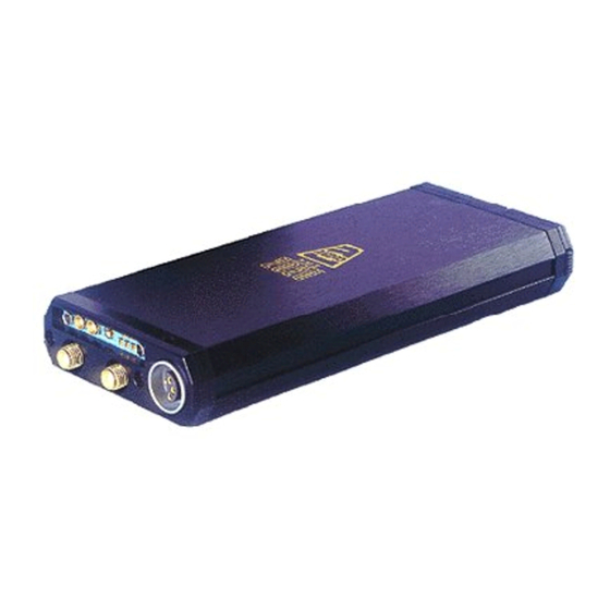
A hand-held transmitter for use with a range of high- quality Schoeps microphone capsules. DX 2020 The diversity receiver in the RMS 2020 System, it can be used as a portable receiver, with a camcorder, or mounted in an RK 2 or DK 2000 rack. - Page 5 DK 2000 Rack Allows up to four DX 2020 receivers to be mounted and powered in a portable rack, with visual and headphone monitoring. All the UHF products from the RMS 2000 range are directly compatible with the RMS 2020 range.
-
Page 6: Diversity Reception
○ ○ ○ ○ The RMS 2020 System provides a choice of 32 operating frequencies, in two banks in the UHF 470MHz to 1000MHz range. This gives the flexibility of allowing several sets of receivers and transmitters to be operated in the same area without interference. -
Page 7: Dx 2020 Receiver
CHAPTER DX 2020 Receiver The DX 2020 diversity receiver in the RMS 2020 range can be used, in conjunction with a TX 2020 or HX 2000 transmitter. Alternatively, up to four DX 2020 receivers can be rack mounted for applications where multiple wireless microphone systems are required. -
Page 8: Setting Up The Dx 2020
• Set the transmitter and receiver to the same operating frequency. • Connect the RX1 and RX2 antennae. • Switch on. • Connect the audio output cable. • Check that one of the RX1 and RX2 indicators is illuminated, and that the ‘No signal’ indicators are not illuminated. -
Page 9: Connecting The Antennae
DX 2020 Receiver Selecting the operating frequency Select the operating frequency you want to use from the label on the side of the DX 2020. Set the F1/F2 switch to F1 (first column of frequencies) or F2 (second column of frequencies). -
Page 10: Technical Specification
DX 2020 Receiver Technical specification ○ ○ ○ ○ ○ ○ ○ ○ ○ ○ ○ ○ ○ ○ ○ ○ ○ ○ ○ ○ ○ ○ ○ ○ Size 147 x 64 x 20mm Weight 250g Temperature range -20˚C to +55˚C Frequency range 470MHz–1000MHz Number of frequencies... -
Page 11: Tx 2020 Pocket Transmitter
LF cut Gain Antenna input Overload indicator Audio input Allows a microphone or line-level input to be connected. LF cut Gives approximately 6dB LF cut at 50Hz, to assist in the reduction of wind noise. F1/F2 Selects between the two banks of 16 frequencies; see Selecting the operating frequency , page 9. -
Page 12: Setting Up The Tx 2020
Connecting the antenna Connect the flexible antenna to the SMA connector. Connecting the audio input Connect the microphone or line level input to the six-pin Lemo connector. Both positive and negative bias voltages are provided, enabling the majority of lavalier... -
Page 13: Technical Specification
TX 2020 Pocket Transmitter Setting the microphone gain The microphone gain control should be adjusted to suit your particular requirements. Select the gain position such that the overload indicators do not illuminate during normal speech. Technical specification ○ ○ ○ ○... -
Page 14: Hx 2000 Hand Held Transmitter
CHAPTER HX 2000 Hand Held Transmitter The HX 2000 is a hand held transmitter for use with the DX 2020 diversity receiver. It provides two switchable frequencies, and can be used with a range of microphone capsules from the Schoeps Colette series. -
Page 15: Setting Up The Hx 2000
HX 2000 Hand Held Transmitter reduction of wind noise. Gain Provides ten gain options; 0 gives minimum gain, and each position increases the gain by approximately 4dB giving a total of 40dB of adjustment. Operation indicator Indicates amber when the unit is on and the battery voltage is within the working range. -
Page 16: Holding The Hx 2000
HX 2000 Hand Held Transmitter These steps are explained below: Fitting the battery Unscrew the battery compartment and insert a DL123A type Lithium battery with the positive end uppermost. Replace the battery compartment. Selecting the operating frequency Set the F1/F2 switch to select the operating frequency. The two available operating frequencies are marked on the label above the battery compartment. -
Page 17: Technical Specification
HX 2000 Hand Held Transmitter Technical specification ○ ○ ○ ○ ○ ○ ○ ○ ○ ○ ○ ○ ○ ○ ○ ○ ○ ○ ○ ○ ○ ○ ○ ○ Length 220mm including capsule Diameter 20mm reducing to 18mm at base Weight 130g Temperature range... -
Page 18: Rk 2 Minirack
Controls, displays, and connections ○ ○ ○ ○ ○ ○ ○ ○ ○ ○ ○ ○ ○ ○ ○ ○ ○ ○ ○ ○ ○ ○ ○ ○ Side panel Antennae LH Receiver Audio output RH Receiver Audio output Power input... -
Page 19: Setting Up The Rk 2
Rk2 Minirack Audio output Provides microphone-level balanced outputs from the two receivers. Power input Allows the receivers to be powered via an external DC supply. Antennae Connects the Rx1 and Rx2 antennae. Front panel The indicators and controls of each receiver are visible from the top of the RK 2 rack. -
Page 20: Setting The Output Phase
Rk2 Minirack Connecting the antennae Connect the antennae to the SMA sockets marked Rx1 and Rx2 on the front panel. Connect the straight antenna to one socket and the right-angled antenna to the other socket. Setting the output phase ○ ○... -
Page 21: Dk 2000 Rack
RF Level bargraphs Displays the RX1 and RX2 RF levels for the selected receiver. Transmitter battery voltage bargraph Displays the transmitter battery voltage for the selected receiver. Audio level bargraph Displays the audio output level from the selected receiver. - Page 22 DK 2000 on, and up to turn the unit off. Headphone level Adjusts the overall output level of the mixed headphone signal. Audio monitor select switches Selects which of receivers are monitored via the headphone output. Display select switches Selects which of the receivers is monitored via the four LED bargraph displays.
-
Page 23: Setting Up The Dk 2000
DK 2000 Rack Internal/External switch Switch the toggle switch to the down position to select internal power, and to the up position for external power. Accessory socket A four-pin Hirose socket allows accessories such as an RK 2 or individual receivers to be powered from the DK 2000 via appropriate cables. -
Page 24: Audio Monitoring
○ ○ To monitor a receiver’s RF levels, transmitter battery voltage, and audio level on the four LED bargraphs press the red DISPLAY SELECT switch. The switch will illuminate to show which receiver is being monitored. To display the DK 2000 battery voltage on the BATT LED bargraph press and hold the red button below the bargraph. -
Page 25: Troubleshooting
CHAPTER Troubleshooting This chapter provides step-by-step troubleshooting procedures for any combination of RMS 2020 System products. Experience has shown that the majority of problems are due to bad batteries, faulty antennae, and faulty cables, as these items are most susceptible to damage. Please check these items first, and check that the LED indicators are correct, before proceeding further. - Page 26 Troubleshooting RK 2 Minirack and DK 2000 Rack ○ ○ ○ ○ ○ ○ ○ ○ ○ ○ ○ ○ ○ ○ ○ ○ ○ ○ ○ ○ ○ ○ ○ ○ Receivers not functioning in the rack • Check that the receivers are pushed firmly home. •...
- Page 27 CHAPTER Cable wiring diagrams Transmitter line/microphone input cable (900-018) ○ ○ ○ ○ ○ ○ ○ ○ ○ ○ ○ ○ ○ ○ ○ ○ ○ ○ ○ ○ ○ ○ ○ ○ XLR 3-pin socket viewed from solder side Lemo 6-pin plug viewed from solder side Receiver/RK 2 output cable...
-
Page 28: Cable Wiring Diagrams
Cable wiring diagrams Receiver/RK 2 output and Betacam power cable (900-016) ○ ○ ○ ○ ○ ○ ○ ○ ○ ○ ○ ○ ○ ○ ○ ○ ○ ○ ○ ○ ○ ○ ○ ○ XLR 3-pin plug viewed from solder side Lemo 6-pin plug Hirose 4-pin plug viewed from solder side... - Page 29 Cable wiring diagrams Headphone output cable (900-063) ○ ○ ○ ○ ○ ○ ○ ○ ○ ○ ○ ○ ○ ○ ○ ○ ○ ○ ○ ○ ○ ○ ○ ○ 0.25" stereo jack socket Lemo 6-pin plug viewed from solder side Microphone wiring for TX 2020 ○...
-
Page 30: Index
Index cable wiring diagrams 27 diversity reception 6 DK 2000 Rack 4, 21 audio monitoring 24 bargraph display 24 connecting power 23 connecting the antennae 23 controls, displays, and connections 21 fitting the batteries 23 fitting the receivers 23 front panel 21... - Page 31 18 fitting the receivers 19 front panel 19 setting up 19 side panel 18 RMS 2020 System 4 technical specification DK 2000 Rack 24 DX 2020 Receiver 10 HX 2000 Hand Held Transmitter 17 TX 2020 Pocket Transmitter 13...
Need help?
Do you have a question about the RMS 2020 and is the answer not in the manual?
Questions and answers