Table of Contents
Advertisement
Quick Links
Advertisement
Table of Contents

Summary of Contents for Home Decor DT830B
-
Page 1: Instruction Manual
OPERATOR’S INSTRUCTION MANUAL DT830B DIGITAL MULTIMETER WARNING READ AND UNDERSTAND THIS MANUAL BEFORE USING THE INSTRUMENT Failure to understand and comply with the WARNINGS and operating instructions can result in serious or fatal injuries and/or property damage. -
Page 2: Specifications
General This instrument is a compact pocket- sized 3 ½ digital multimeters for measuring DC and AC Voltage, DC Current, Resistance and Diode, transistor measurement. Low battery voltage indication is provided. It’s ideal instruments for use in fields, such as laboratory, workshop, DIYers and home applications. - Page 3 FREQUENCY RANGE: 45Hz ~ 450Hz OVERLOAD PROTECTION: 1000V DC or 750V rms for all ranges. DC CURRENT RANGE RESOLUTION ACCURACY 2000uA 0.1uA ±(2.0% of rdg +2D) 2000uA ±(1.8% of rdg +2D) 20mA 10uA 200mA 100uA ±(2.0% of rdg +2D) 10mA ±(2.0% of rdg +10D) OVERLOAD PROTECTION: 500mA 250V fuse (10A range unfused).
-
Page 4: Dc & Ac Voltage Measurement
damage of the instrument, do not measure voltages that might exceed 500V above earth ground. Before the use of instrument, inspect test leads, connectors and probes for cracks, breaks, or crazes in the insulation. DC & AC VOLTAGE MEASUREMENT Connect red test lead to “V mA” jack, Black lead to “COM”... -
Page 5: Resistance Measurement
in with current is to measure. Read current value on Digital Display. Additionally, “10A” function is designed for intermittent use only. Maximum contact time of the test leads with the circuit is 15 seconds, with a minimum intermission time of seconds between tests. RESISTANCE MEASUREMENT Red lead to “V mA”. -
Page 6: Battery And Fuse Replacement
Determine whether the transistor is PNP of NPN type and locate the Emitter, Base and Collector leads. Insert the leads into the proper holes of the hFE Socket on the front panel. The meter will display the approximate hFE value at the condition of base current 10µA and V 2.8V. - Page 7 - 7 -...
-
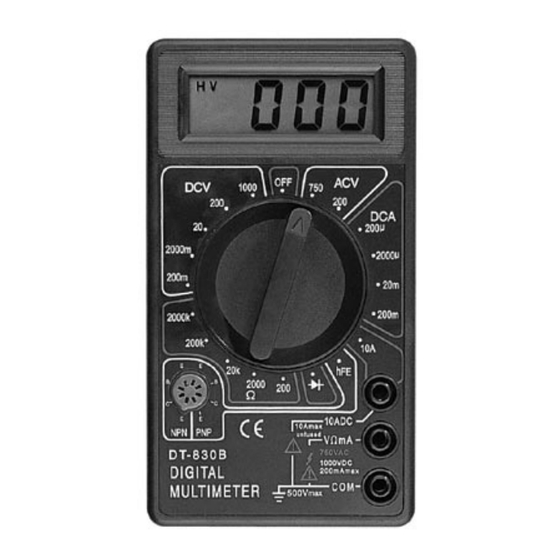
Page 8: Front Panel Description
FRONT PANEL DESCRIPTION FUNCTION AND RANGE SWITCH This switch is used to select the function and desired range as well as to turn on the instrument. To extend the life of this battery, the switch should be in the “OFF” position when the instrument is not in use.
Need help?
Do you have a question about the DT830B and is the answer not in the manual?
Questions and answers