Table of Contents
Advertisement
Quick Links
Advertisement
Table of Contents

Related Manuals for WisyCom MFL

Summary of Contents for WisyCom MFL
- Page 1 MFL User Manual RF over Fiber System Up to 4 ch’s in a single mode fiber Diversity reception antenna remoting IFB transmissions remoting Integrated tunable filters Optical & RF power meter Ethernet conn. for remote control ...
- Page 2 MFL User Manual rev.02 ...
-
Page 3: Brief Description
MFL User Manual RIEF DESCRIPTION MFL provides wideband optical link for up to 4 RF channels combined in one single mode fiber thanks to CWDM technology. It is designed to allow for a flexible and modular configuration thanks to a mainboard that can be fitted with up to 4 plug‐in boards that can be chosen any combination of two types: • TX: Laser optical transmitter, (CDWM) plug‐in board • RX: Optical‐receiver plug‐in board Example of some possible configurations: ‐ MFL‐TTTT is a 4 laser transmitters on channel 51/53/55/57 (λ = 1510/1530/1550/1570 nm). ‐ MFL‐RRRR is a 4 optical receiver on channel 51/53/55/57 ‐ MFL‐RRTT has 2 receiver on ch. 51/53 and 2 transmitters ch. 55/57 (it works with MFL‐TTRR) ‐ MFL‐TTRR has 2 transmitter on ch51/53 and 2 receiver on ch. 55/57 (it works with MFL‐RRTT) Main features: CWDM LASERs to fit many RF channels over a single fiber LOW NOISE DESIGN to allow great coverage when used to remote receiving antennas HIGH INTERFERENCE IMMUNITY thanks to high IIP3 design and a control/compensation of gain EASY TO USE thanks to integrated RF/optical power meter and optical power compensation DIGITALLY TUNABLE FILTERS 25 MHz bandwidth, center frequency tunable over 404‐788 MHz (optional) INTEGRATED FAILSAFE REDUNDANCY: It can route RF through an external filter or to additional receiver (redundancy) to easily implement a failsafe configuration that can switch on a redundant receiver or transmitter if any fault is detected IFB MODE: It can route an IFB high power signal to transmit locally and send IFB carrier over fiber to slave units. When it is working along with a MTK952MS in slave configuration, the fiber loss is automatically recovered and the unit increases the gain so that the transmitter power equals the target level (measured with an power/SWR meter integrated into the MTK952MS) REMOTE MONITOR/CONTROL: thanks to a data link on Ethernet 10/100 Base Tx ... -
Page 4: Safety Instruction
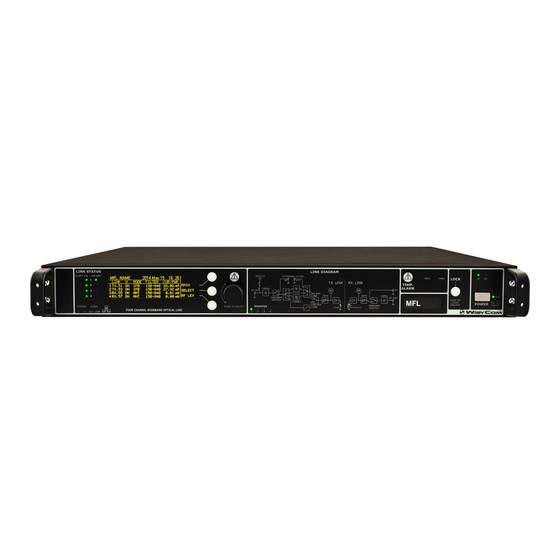
MFL User Manual rev.02 AFETY INSTRUCTION Read this safety instruction and the manual first Follow all instructions and information. Do not lose this manual. Do not use this apparatus under the rain or near the water. Do not install the apparatus near heaters or in hot environments, do not use outside the operating temperature range. Mount the apparatus as indicated in the instruction, do not block side grids for air ventilation ATTENTION: supply the apparatus with a correct mains voltage and with the ground connection. Check the power cord integrity. The power cord must be protected from damage Do not install the apparatus near heaters or in hot environments, do not use outside the operating temperature range. Do not open the apparatus, only qualified service technician are enabled to operate on it. The apparatus needs servicing when it is not properly working or is damaged by liquids, moisture or other objects are fallen inside the apparatus. Use only accessories or replacement parts authorized or specified by the manufacturer. Clean the apparatus only with dry cloths, do not use liquids. The ON/OFF is a double pole circuit breaker, but to ensure the complete disconnection of the apparatus, disconnect the power cord. Report the serial number and the purchasing date in front of the manual. It is needed to have proper replacement parts or accessories from the manufacturer. When replacement parts are needed, use only replacement parts authorized from the manufacturer. Substitution with not authorized parts could result in electric shock, hazards or fire. Keep attention on all the labels with warnings or hazards on the apparatus. Optical Safety!!! ... - Page 5 MFL User Manual RONT ANEL ONTROL AND UNCTIONS MFL allows an easy and quick configuration using buttons, push knobs and display. A C The front panel is functionally divided in the following section: A – LINK STATUS ❹ Transmitter / Receiver configurations ❺ ❶ ❷ ❸ ❶ Connection status: The first column of LEDs indicate Alarms The ON column indicate if a module is ON The FAILSAFE column indicate if the Failsafe option is enabled STATUS and CONN, showing the LED indications of the Ethernet module on the rear panel ❷ Display (64 x 256 pixels yellow OLED display) ❸ 3 push buttons (membrane). The function of each button (upper, middle and lower) will be readable from the contextual menu on the display. ❹ Warning (YELLOW) and Alarm (RED) light indicator ...
-
Page 6: Rear Panel
MFL User Manual rev.02 EAR ANEL ❶ ❷❸ ❹ ❺ ❻ ❼ ❽ ❾ ❿ ⓫ ⓬ ⓭ ⓮ ⓯ ⓰ ⓱ ⓲ ⓳ ⓴ ❶ AC Power Plug AC mains power input, IEC Connector 90‐264 Vac ❷ Product label with Serial Number and Options installed ❸ Ground point To connect the MFL rack frame to ground ❹ DC Power Plug (only with MFL‐DC option) DC power input, 10‐28Vdc, Max 5A ❺ Ethernet socket (RJ45) for connection to a network or computer ❻ Auxiliary optical Input/Output Connector ❼ Optical Input/Output Connectors where the optical signals are divided by wavelength ❽ Optical Input/Output Connector where the optical signals are multiplexed (only with MFL‐OMX option) ❾ Optical safety label ❿ Output N connector female 50Ω (*) ⓫ Orange label: relative laser wavelength = 1570 nm ⓬ Output N connector female 50Ω (*) ⓭ Yellow label: relative laser wavelength = 1550 nm ⓮ Input N connector female 50Ω with switchable 12V boosting power (only on transmitter modules) (*) ⓯ Green label: relative laser wavelength = 1530 nm ⓰ Input N connector female 50Ω with switchable 12V boosting power (only on transmitter modules) (*) ⓱ Blue label: relative laser wavelength = 1510 nm ⓲ BNC‐F connector 50Ω for failsafe option (on receivers modules) (*) ⓳ BNC‐F connector 50Ω to connect the output of an external filter (on transmitters modules) (*) ⓴ BNC‐F connector 50Ω to connect the input of an external filter or for failsafe option (on transmitters modules) (*) ... - Page 7 MFL User Manual ISTEM VERVIEW The system is composed by a MFL‐BASE (1U rack frame) and some optional/modular boards to build the desired configuration. MFL‐BASE can have up to 4 optical modules that can be either TX or RX (factory installed) to adapt the unit to several configurations. To simplify the usage we give a name of the final configuration that easy identify the CWDM channels and a color code for the RF connectors (N type). We use as default 4 laser wavelength although the CWDM standard can allow to use much more with a 20nm wavelength separation: ‐ Channel 51 short name for wavelength 1510 nm ‐ Channel 53 short name for wavelength 1530 nm ‐ Channel 55 short name for wavelength 1550 nm ‐ Channel 57 short name for wavelength 1570 nm Channel Wavelength Color Identifier 51 Wavelength 1510 nm laser, single mode Blue 53 Wavelength 1530 nm laser, single mode Green Wavelength and Color Coding: 55 Wavelength 1550 nm laser, single mode Yellow 57 Wavelength 1570 nm laser, single mode Orange For example: NAME (i.e.) ...
-
Page 8: System Description
MFL User Manual rev.02 YSTEM DESCRIPTION TRANSMITTER MODE ‐ ‐ ‐ MFL-T*** wideband optical link CWDM Antenna External Filter Frequency Booster (Failsafe) #51 = 1510nm (+12VDC) #53 = 1530nm #55 = 1550nm RF Power #57 = 1570nm... - Page 9 MFL User Manual YSTEM ESCRIPTION RECEIVER MODE ‐ ‐ ‐ MFL-R*** wideband optical link CWDM Frequency #51 = 1510nm #53 = 1530nm Optical Power Meter #55 = 1550nm RF-IN (Failsafe) #57 = 1570nm Gain 140 MHz RF-OUT...
-
Page 10: Configuration Example
#53 = 1530nm #55 = 1550nm #55 = 1550nm #57 = 1570nm #57 = 1570nm MFL-T-T- (redundant link) MFL-TT** (redundant link) MFL-RR** (redundant link) MFL-R-R- (redundant link) Example of a redundancy link (1-fault tolerance) with automatic failsafe switches Above an example of remote diversity reception with MFL‐T‐T‐ in the remote site and MFL‐R‐R‐ in local site (i.e. OB van or main ... - Page 11 Switch Optical #55 = 1550nm #55 = 1550nm #57 = 1570nm #57 = 1570nm MFL-TTTT (redundant link) MFL-RRRR (redundant link) Example of a redundancy link (1-fault tolerance) with automatic failsafe switches Above an example of remote diversity reception using all of 4 plug‐in modules available: MFL‐TTTT in the remote site and MFL‐RRRR ...
- Page 12 MFL User Manual rev.02 ONFIGURATION EXAMPLE EMOTE IVERSITY AND Remote Local Diversity Diversity Reception Reception single-mode MFL-TTRR MFL-RRTT wideband optical link wideband optical link Antenna External Filter Booster (Failsafe) (+12VDC) TX.51 RF Power Optical Power Meter Meter RF-IN (Failsafe) 140 MHz RX.51 Mode: ANT ...
-
Page 13: Oled Display
MFL User Manual OLED ISPLAY MFL Info screen Switch on the MFL and by pushing the rotary knob (at the right of the display) all the basic information are displayed: ❶ Product name ❷ Serial number ❸ Class and Hardware version ❹ Firmware version ❺ Application Firmware version Push the rotary knob to enter the Main screen Main screen In the left top side of the main screen there is the “NAME” of the MFL that is settable in the Main menu. At the right of "NAME", date and time are displayed. The first number (1 to 4) identify the link (same reference on back‐side connectors). TX or Rx if that link has a laser transmitter or a receiver, respectively. The last number after the dot, 51/53/55/57 refers to the CWDM link frequency: 1510/1530/1550/1570nm. ON/OFF status of specific link There are 2 possible modes: ‐ ANT as remote antenna link ‐ IFB as remote intercom link optimized on a 0dBm reference input CWDM Antenna External Filter Frequency Booster (Failsafe) #51 ... - Page 14 MFL User Manual rev.02 Menu Tree Name Optical connectors CONN# 1 / 2 / 3 / 4 / 5 DISPLAY brightness 1÷15 DISPLAY timeout 5÷120 IP Address Serial FW ver Boot ver App FW ver Main Board ...
- Page 15 MFL User Manual Status ON/OFF Mode IFB / ANT Filter 150‐840 / 470‐840 / BPF / EXTERN Central freq. 404÷788 MHz BP filter center freq. (Bandwidth 25MHz) With IFB Mode: ‐23.5 ÷ 8.0 dB With ANT Mode & filter: Gain ‐ BPF: ‐28.0 ÷ 3.5 dB ‐ EXTERN: ‐22.0 ÷ 9.5 dB ...
- Page 16 MFL User Manual rev.02 Status ON/OFF Mode IFB / ANT ‐13.5 ÷ 18.0 dB Gain Failsafe enabled / disabled Optical power Optical pwr. corr. ON / OFF ...
- Page 17 MFL User Manual Main menu From the Main screen, pushing the upper right button, it’s possible to enter on the main menu options: Name: to change the name of the MFL shown in the Main screen. 12 alphanumeric characters (A‐Z, a‐z, 0‐9, case‐sensitive) Optical connectors: parameter that show the configuration and the optical attenuation of the 5 optical connectors DISPLAY brightness: To set the brightness of the OLED display. 0÷15 step 1 (default 0) DISPLAY timeout: to set the display timeout before decrease the brightness of the OLED display and before returning to Main screen. (default 30 seconds) ...
- Page 18 MFL User Manual rev.02 TX Link menu From the Main screen, pushing the rotary knob, it’s possible to enter on the selection screen and then, pushing the upper right button on the desiderate transmitter module, it’s possible to enter on the TX Link menu: Status: status of the transmitter (default ON) Mode: working mode selection: ‐ ANT for remote antenna reception ‐ IFB for remote intercom for iso‐frequency areas NOTE: set the transmitter module and the receiver module with the same working mode (as in the third configuration example) (default ANT mode) Filter: Type of RF filter (only for ANT mode) ...
- Page 19 MFL User Manual Ext filter att.: Attenuation of the external filter, that can be set by user from 0.0 to 6.0dB with step of 0.5dB. (default 2.0dB) BF filter: here it’s possible to see all the Band‐Pass filter information: Example ID ID of the RF filter TBF01 Serial Serial number of the RF filter T1541322 App FW ver. Application firmware version of the RF filter 1.0 Center freq. range Center frequency range of the RF filter 404 ‐ 788 MHz Filter bandwidth Filter bandwidth 25 MHz Transmitter param: here it’s possible to see all the transmitter parameters: Example ...
- Page 20 MFL User Manual rev.02 RX Link menu From the Main screen, pushing the rotary knob, it’s possible to enter on the selection screen and then, pushing the upper right button on the desiderate receiver module, it’s possible to enter on the RX Link menu: Status: status of the transmitter (default ON) Mode: working mode selection: ‐ ANT for remote antenna reception ‐ IFB for remote intercom in isofrequency areas applications (default ANT mode) Gain: Settable gain from ‐13.5 to 18.0dB with step of 0.5dB. (typ.) (default 0.0dB) ...
-
Page 21: Alarm List
MFL User Manual Alarm List When an alarm occurs, the MFL can show one or more of the following warnings: A. Show a message on the display B. Turn on the yellow or red alarm led C. Light up an auxiliary LED (in some cases) D. Insert the alarm on the current alarm list and in the “history” alarm list (in MAIN>Info>Alarms menu) Current alarm list: pushing the rotary knob, it’s possible to enter in the current alarm list where are displayed the number and type of current alarms in the general apparatus or in each module ... - Page 22 MFL User Manual rev.02 The alarm can be related to a specific transmitter/receiver or general. Shown below the complete alarms list: Auxiliary LED Name Code Message on display (A) Alarm LED (B) Alarm list (D) (C) E2_INVALID 0x06 Invalid int memory FIXED RED ‐ ‐ E2_INVALID_COPY1 0x80 Calibration data copy #1 invalid FIXED YELLOW ‐ Cal data copy1 invalid E2_INVALID_COPY2 0x81 Calibration data copy #2 invalid FIXED YELLOW ‐ Cal data copy2 invalid E2_CRC_DIFF 0x07 Calibration data copies differ FIXED RED ‐ ‐ E2_ERROR_UPDATE_CRC 0x08 ...
-
Page 23: Troubleshooting
they haven't been installed PWR_SUPPLY Abnormalities were noted in the power supply of the machine. ‐ check if the two fans work properly (check alarms code 0x02 or 0x03 on the alarm list) TEMP One of the temperature sensors measures a temperature > 60°C ‐ switch off the MFL for cooling and check the location temperature ‐ clean the ventilation grids I2C0 Error on I2C0 bus I2C1 Error on I2C1 bus FAN1 The fan on the left (#1) doesn’t turn ‐ switch off and switch on the MFL FAN2 The fan on the right (#2) doesn’t turn ‐ switch off and switch on the MFL Communication error with the temperature sensor of the main TEMP_SENS board LOW_BATT This message informs that the backup battery is running low I‐th link not found. The error is detected in the initialization phase when attempting to communicate with the E2 memory on the LINK__NOT_FOUND module to establish if the module is present or not. Note: The link is not considered valid and therefore will not be present among those available I‐th link of type different from that stated in the E2 memory. - Page 24 MFL User Manual rev.02 LINK__ON_OFF There was an error in the phase of power ON/OFF of a link This alarm appear when the Failsafe is activated in a receiver and LINK__FAILSAFE_RX the optical signal is lost This alarm appear when the Failsafe is activated in a transmitter LINK__FAILSAFE_TX and the laser current goes out of range (the TX module doesn't work properly) LINK__BOOSTER It was detected a malfunction in the power of the booster LINK__LASER_EOL The laser has terminated its life time It was detected a communication problem with the temperature LINK__TEMP_SENS sensor of the laser module If a problem not listed in the above table occurs or if the problem cannot solved with the proposed troubleshooting, please contact support service at support@wisycom.com or sales@wisycom.com. ...
-
Page 25: Specification
MFL User Manual TECHNICAL SPECIFICATION Mainframe RF to Optical modules (TX module) : 1 to 4 Optical to RF modules (RX module) : 1 to 4 Maximum number of modules : 4 RF to fiber link working modes : 2 (“ANT” mode or “IFB” mode) Rear optical connectors : 5 SC/APC, other type on request Internal optical CWDM MUX/DEMUX : 2 max (option MFL‐OMX) “ANT” mode RF TX characteristics Typical application : RX antenna remoting Frequency ranges (front panel selectable) : ‐ 140 to 840 MHz (flat) ‐ 470 to 840 MHz ‐ 25MHz BW tunable band‐pass filter (opt*) (center freq. in 1MHz step, from 404 to 788 MHz) ... - Page 26 MFL User Manual rev.02 ...
-
Page 27: Environmental Information
MFL User Manual ENVIRONMENTAL INFORMATION Applicable in the European Union and other European countries with separate collection systems Disposal of Old Electrical & Electronic Equipment (2002/96/EC) This symbol indicates that this products shall not be treated as household waste. Instead it shall be handed over to the appropriate collection point for the recycling of electrical and electronic equipment. The recycling of material will help to conserve natural resources. ITALY ONLY Obblighi di informazione agli utilizzatori ai sensi dell’art. 13 del Decreto Legislativo 25 luglio 2005, n. 151 “Attuazione delle Direttive 2002/95/CE, ... - Page 28 MFL User Manual rev.02 Wireless System Communications Via Spin 156 I‐36060 Romano d’Ezzelino Italy Tel. +39 ‐0424 ‐382605 Fax +39 ‐ 0424 ‐ 382733 www.wisycom.com e‐mail: sales@wisycom.com ...
Need help?
Do you have a question about the MFL and is the answer not in the manual?
Questions and answers