Advertisement
Quick Links
Advertisement

Subscribe to Our Youtube Channel
Related Manuals for Richmond FUJI FA-200

Summary of Contents for Richmond FUJI FA-200
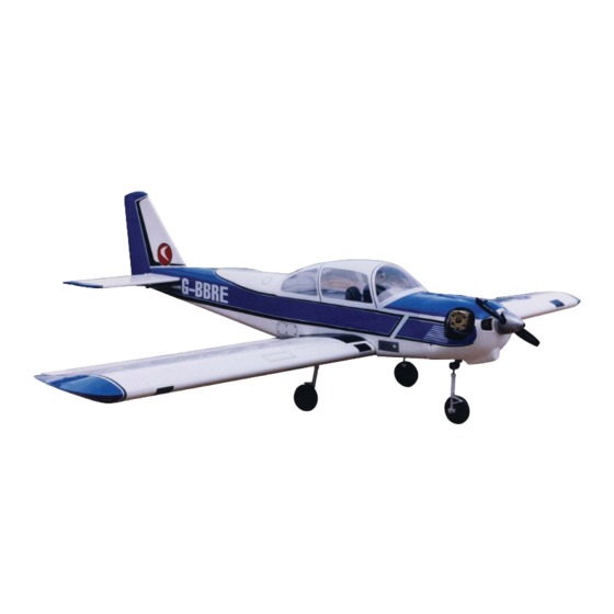
- Page 1 FUJI FA-200 AERO SUBARU SEMI SCALE SPORT MODEL AERO SUBARU Assembly Operations Manual Please review this manual throughly Before assembling or Operating AERO SUBARU Semi scale sport model We’ve used our ULTRA TOUGH POLYCOTE ECS Enhanced Covering System for this Model...
- Page 2 Stage 1 – WING ASSEMBLY. JOINING THE WING HALVES Parts needed Tools and Adhesives needed - Right/left wing panels - Rolled trim strip (supplied with kit) - Wing joiner (also called dihedral brace) - 30 minute epoxy - Two short dowel guides - Epoxy brush or stir sticks - Disposable mixing dish for the epoxy - Sandpaper (Coarse 240 grit recommended)
- Page 3 Center line 1.6 Wipe off the excess epoxy 1.5 Carefully insert the joiner all the way to the center line Stage 2 When the glue has cured in Stage 1, trial fit the second wing panel onto the first to ensure that the two panels fit without an excessive gap.
- Page 4 FITTING AILERON SERVOS Stage 4 To install the aileron servos into the wing you will need the following items : - 2 servos - Servos mounting screws and grommets as supplied with servos. - Servo control arms as supplied with the servos. - Two aileron control rod assemblies supplied with the kit.
- Page 5 Step 3 Ensure that the aileron control horns are screwed onto the threaded aileron control horn bolts and that both control horns are in approximately the same place on their respective bolts. Step 4 Connect the aileron servo rods to the aileron control horns.The one end with clevis will be attached to the servo output arm.
- Page 6 6.4 Install servo to the servo 6.5 Install the control horn to the 6.6 Final flap installation mount flap 6.7 Flap up position 6.8 Flap down position To install the stabilizers to the fuselage you will need: FITTING THE HORIZONTAL AND VER- - Fuselage TICAL STABILIZERS - Vertical stabilizer with pre-installed rudder...
- Page 7 Stage 8 Check the fit of the horizontal stabilizer in its slot. Make sure the tail is square and centred to the fuselage by taking measurements as shown in the dia- Equal distance grams on the right, but don not glue any- thing yet.
- Page 8 Stage 11 Now apply sufficient epoxy to the top and bottom of the Insert the horizontal stabilizer in its slot in the fuselage horizontal stabilizer. Use 30 minute epoxy to ensure a and re-check the alignment. Excess epoxy should be strong bond and give yourself plenty of working time.
- Page 9 Stage 14 Insert the vertical stabilizer in its slot in the fuselage Now apply sufficient epoxy to both sides and the bottom and re-check the alignment. Excess adhesive should of the vertical stabilizer. Use 30 minute epoxy to ensure be cleaned off with a rag or tissue before it cures. a strong bond and give yourself plenty of working time.
-
Page 10: Installing The Engine
pressure line 50 mm (2 in) for pressure line 100 mm (4 in) for fuel line fuel line 16.2 Use 100 mm (4 in) for fuel line 16.3 Illustration of fuel line posi- 16.4 Fuel tank installed on the and 50 mm (2 in) for pressure line tioning inside the tank power module INSTALLING THE ENGINE... -
Page 11: Installing The Cowl
18.2 Place the steering arm with pre-install EZ 18.3 Slide the nose gear to the bearing, passing connector to the nylon nose gear bearing through the steering arm. Secure the steering arm to the nose gear by tighting the hex-nut to the mark on the nose gear. -
Page 12: Installing The Servos
Elevator control horn location 20.2 Elevator control horn location 20.3 Rudder control horns loca- 20.4 Elevator and rudder control tion horn connected to the control rod INSTALLING THE SERVOS Stage 21 Install the rubber servo grommets and brass ferrules supplied with your radio equipment. - Page 13 Elevator pushrod Throttle pushrod Nose gear pushrod Rudder pushrod 22.3 Connect clevises on pushrods to the servo arms first, then 22.2 Pre-installed elevator, throttle and rudder pushrod install the servo arms to the servos CONNECTING THE PUSHRODS TO THE ELEVATOR Stage 23 Connect the elevator servo to the receiver and turn on your transmitter.
- Page 14 ADJUST CONTROL SURFACE THROW LIMITS. Stage 26 Adjust the deflection of the control surfaces to match the specifications on page 15 You can reduce the amount of throw by doing either or both of the following: - From the servo end, move the clevis or EZ connector to a hole in the servo arm that is closer to the servo output shaft.
- Page 15 Stage 29 INSTALLING THE RECEIVER BATTERY 29.1 Consult your radio manual for instructions about hooking up your receiver battery, receiver and switch harness. 29.2 Wrap the battery pack securely in foam suitable for RC equipment and wrap the foam insulated pack in a plas- tic bag or cling wrap.
- Page 16 Stage 33 CONFIRM MECHANICAL INTEGRITY 33.1 Once you have confirmed that the CG is correct, you should do a thorough review of the entire model before your first flight. Check every- thing twice! Every hook up, every coupling, every- thing! Do it twice!! 33.2 Before your first flight , have an experienced 80 - 85 mm flyer review your work.
Need help?
Do you have a question about the FUJI FA-200 and is the answer not in the manual?
Questions and answers