Table of Contents
Advertisement
Advertisement
Table of Contents

Summary of Contents for LOYTEC L-STAT
-
Page 1: User Manual
L-STAT L-STAT™ Room Operator Panel User Manual LOYTEC electronics GmbH... - Page 2 Version 1.0 Document № 88085801 LOYTEC MAKES AN D YOU RECEIVE N O WARRAN TIES OR CON DITION S, EXPRESS, IMPLIED, STATUTORY OR IN AN Y COMMUN ICATION WITH YOU, AN D LOYTEC SPECIFICALLY DISCLAIMS AN Y IMPLIED WARRAN TY OF MERCH AN TABILITY OR FITN ESS FOR A PARTICULAR PURPOSE.
-
Page 3: Table Of Contents
L-STAT User Manual LOYTEC Contents 1 Introduction ....................7 Overview ......................7 Key Features ......................8 LCD Segments ..................... 9 2 Quick-Start Guide ..................13 Hardware Installation ..................13 User Interface ....................14 2.2.1 General Description ................. 14 2.2.2 Operating Modes ..................15 2.2.3 Access Levels ................... - Page 4 L-STAT User Manual LOYTEC 8 Specifications ....................58 Physical Specifications ..................58 Sensor Specifications ..................58 9 References ....................60 10 Revision History ..................61 Version 1.0 LOYTEC electronics GmbH...
- Page 5 L-STAT User Manual LOYTEC Abbreviations ASCII ........American Standard Code for Information Interchange IR ........Infrared LCD........Liquid Crystal Display NDEF ........NFC Data Excahnge Format NFC ........Near Field Communication RGB ........Red, Green, Blue URI ........Uniform Resource Identifier URL........
-
Page 7: Introduction
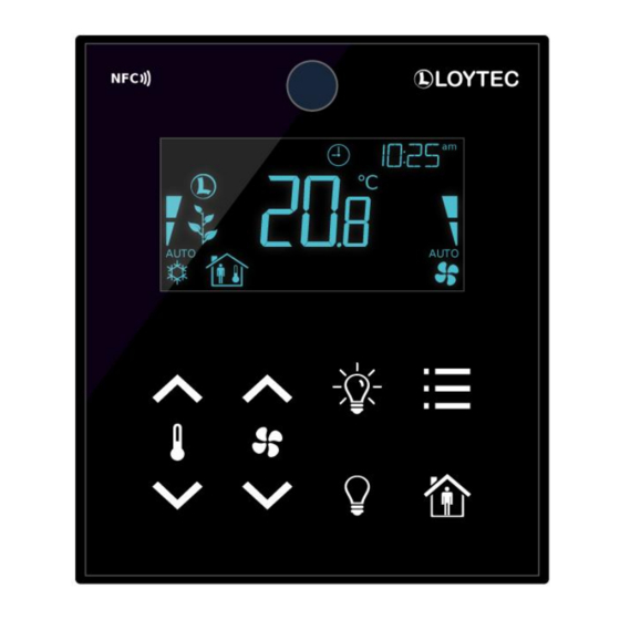
LOYTEC 1 Introduction 1.1 Overview The L-STAT is a room control device with a modern look that fits any interior design. It is directly connected to a LOYTEC controller with a Modbus interface such as LIOB-AIR, L- ROC or L-INX. -
Page 8: Key Features
L-STAT User Manual LOYTEC 1.2 Key Features The different L-STAT models and their features are documented in Table 1. Features LSTAT-800-Gx-Lx LSTAT-801-Gx-Lx LSTAT-802-Gx-Lx Modbus RTU Slave NFC Tag Buzzer Internal ... -
Page 9: Lcd Segments
The following Figure shows the LCD of the L-STAT with all possible segments. Figure 1: LCD Segments available on L-STAT The following Table gives an overview of all available segments of the L-STAT LCD with its defined names. The Table also shows which symbols are directly accessible via Modbus registers (see Table 12 on Page 26). - Page 10 L-STAT User Manual LOYTEC Direct Segment Name Description Access clock Clock symbol sun_left Left half of sun symbol sun_right Right half of sun symbol moon Moon symbol Colon of the secondary display It will only be accessible if the ...
- Page 11 L-STAT User Manual LOYTEC Direct Segment Name Description Access wind Wind alarm symbol rain Rain alarm symbol window Window open alarm symbol Fan symbol valve Valve symbol logo Loytec logo symbol green_leaf_3 ...
- Page 12 L-STAT User Manual LOYTEC Direct Segment Name Description Access The main display is primarily used to main_display show certain values. It is not accessible directly. unit_F unit_C unit_cfm unit_l/s All unit symbols are not directly accessible but are displayed along with a unit_m³/h...
-
Page 13: Quick-Start Guide
LOYTEC 2 Quick-Start Guide 2.1 Hardware Installation Please refer to the L-STAT installation sheet for further information on dimensions, mounting and wiring. Figure 2 shows the back view of the device with the connection terminals for Modbus, 24 V DC-Supply and external buttons. The four external buttons share a common GND... -
Page 14: User Interface
L-STAT User Manual LOYTEC 2.2 User Interface 2.2.1 General Description The user interface consists of the LCD for displaying any desired value and up to eight touch buttons which are used to adjust set points and change settings. Additionally up to four external push-buttons can be connected to the device. -
Page 15: Operating Modes
LOYTEC 2.2.2 Operating Modes In Figure 4 the operating modes of L-STAT are depicted. Each operating mode gives access to certain Modbus registers that can either be viewed or edited depending on the mode. The following data is available on L-STAT: ... -
Page 16: Access Levels
Table 4: Operating Modes 2.2.3 Access Levels The L-STAT has two access levels (end user & system administrator) with configurable rights to display and edit values. Each access level is secured by a four digit pincode that will be requested when EDIT-mode or DIRECT_ACCESS-mode is entered if the desired value is pincode protected. -
Page 17: Device Settings
L-STAT User Manual LOYTEC 2.2.4 Device Settings The following Table gives an overview of the device settings accessible through the button interface as well as via Modbus. For the corresponding Modbus registers please refere to Table 18, Table 19 and Table 20 on Page 30 and following. -
Page 18: Factory Default
The factory default configuration for display values and set points depends on the specific L-STAT model. The following Table shows the factory default values for each model. See Table 28 on Page 39 for display value configuration and Table 29 on Page 41 for set point configuration. -
Page 19: Getting Started With The Configurator
2.3 Getting Started with the Configurator A Modbus Template for the L-INX configurator with all available datapoints can be downloaded from the Libraries/Templates Download section on the LOYTEC website: https://www.loytec.com/support/download For further information on using the L-INX configurator for Modbus devices please refer to the L-INX/L-GATE user manual [1]. -
Page 20: Modbus
3 Modbus 3.1 Introduction The L-STAT operates as a Modbus slave in Modbus RTU mode. The default baudrate is set to 57600, the default parity is set to ‘none’ and the default address is set to 1. The communication with a Modbus master device will work with Modbus function code 0x03 (Read Holding Registers). -
Page 21: Modbus Register Usage For Value Display
L-STAT User Manual LOYTEC 3.3 Modbus Register Usage for Value Display The following Figure 6 shows, which Modbus registers have influence on a displayed value, unit, text on the secondary display or symbols. Depending on settings in configuration registers different combinations are possible to achieve the desired result. -
Page 22: Modbus Register Description
32 (see Table 9 on Page 24). SPC: Set point changed flag, is set when a set point was changed on the L-STAT. Each set point has an individual change flag at register address 3 (see Table 8 on Page 23). - Page 23 L-STAT User Manual LOYTEC Register Bit Position Register Name Address change_flags_ SP15 SP14 SP13 SP12 SP11 SP10 set_points 0x0003 change_flags_ device_settings 0x0004 change_flags_ OV15 OV14 OV13 OV12 OV11 OV10 offset_values 0x0005 The change flag register states will remain true until the flags are cleared by the Modbus master by writing a logical ‘1’...
- Page 24 L-STAT User Manual LOYTEC Register Bit Position Register Name Address ir_remote_control_ button_code remote_id command 0x0020 [0x00] [0x00] This register provides the button_code and remote_id of a valid command received via the infrared receiver. See Chapter 5 for detailed information. Whenever a command was received the ir_remote_control_command register is updated and the IRC flag of the short_pressed register at address 1 is set (see Table 7 on Page 22).
- Page 25 L-STAT User Manual LOYTEC Register Bit Position Register Name Address display_value_0 [0x0000] 0x0040 display_value_1 [0x0000] 0x0041 display_value_2 [0x0000] 0x0042 display_value_3 [0x0000] 0x0043 display_value_4 [0x0000] 0x0044 display_value_5 [0x0000] 0x0045 display_value_6 [0x0000] 0x0046 display_value_7 [0x0000] 0x0047 display_value_8 [0x0000] 0x0048 display_value_9 [0x0000] 0x0049...
- Page 26 0x8200 – This means that set_point_0 is currently edited by the system administrator in EDIT-mode. For a listing of all L-STAT operating modes see Table 4 on Page 16. Table 13: User Interface Direct Access Version 1.0...
- Page 27 L-STAT User Manual LOYTEC Register Bit Position Register Name Address buzzer_direct_ buzzer_duration access_0 0x0066 [0x00] buzzer_direct_ buzzer_mode buzzer_tone access_1 0x0067 [0x00] [0x00] These registers are used to provide direct access of the piezo buzzer primarily used to give acoustic feedback for the touch buttons.
- Page 28 32 bit timestamp in seconds since JAN-01-1970. The timestamp is incremented by the L-STAT device but anyway it has to be set by the master at startup or at defined intervals to prevent time offsets. The timestamp is compatible with the L- INX system time register.
- Page 29 [0x0000] modbus_time_cleared_0 and modbus_time_cleared_1 represent a 32 bit timestamp in seconds since JAN-01-1970 that is set by the L-STAT device after the statistics have been cleared by the master device. All other values are 32 bit counters incremented by the L-STAT device. These values are not permanently stored at the L-STAT and will be lost after a reboot.
-
Page 30: Device Settings
L-STAT User Manual LOYTEC 3.4.2 Device Settings The device settings contain data to configure the device and the user interface. This registers are also accessible through the button interface in EDIT-mode for the system administrator. The data is stored persistently and will be preserved during power loss. - Page 31 L-STAT User Manual LOYTEC Register Bit Position Register Name Address reserved color_brightness lcd_color_red 0x00B3 [0x00] [0x64] reserved color_brightness lcd_color_green 0x00B4 [0x00] [0x64] reserved color_brightness lcd_color_blue 0x00B5 [0x00] [0x64] lcd_brightness_ lcd_contrast lcd_brightness contrast 0x00B6 [0x64] [0x64] user_interface_ lcd_color_scheme Time Date settings...
- Page 32 L-STAT User Manual LOYTEC Register Bit Position Register Name Address occupancy_sensor_ occupancy_timeout config 0x00B8 [0x0A] With this register the function of occupancy sensor is enabled and controlled. occupancy_timeout: defines a timeout in seconds when the state of the occupancy flag of the present state and short pressed register at address 0 and 1 will be cleared again after motion was detected.
-
Page 33: Configuration Registers
0x0 – K 0x1 – °C (SI) 0x2 – °F (US) DU: display_unit, defines which unit system is used to display values on the L-STAT. The following values are possible: 0x0 – access prohibited via the user interface 0x1 – °C (SI) 0x2 –... - Page 34 L-STAT User Manual LOYTEC Register Bit Position Register Name Address 0x00C8 secondary_display_ sec_display_direct_access_string – direct_access_string 0x00CF The string will be displayed with the 4x16 segment digits of the secondary display. The string will be updated if the secondary_display_direct_access_enabled flag at the config_flags register at address 192 (Table 22 at Page 33) is set.
- Page 35 L-STAT User Manual LOYTEC Register Bit Position Register Name Address config_touch_ set_point_index button_0 0x00D0 [0x00] config_touch_ set_point_index button_1 0x00D1 [0x01] config_touch_ set_point_index button_2 0x00D2 [0x00] config_touch_ set_point_index button_3 0x00D3 [0x00] config_touch_ set_point_index button_4 0x00D4 [0x00] config_touch_ set_point_index button_5 0x00D5 [0x01]...
- Page 36 L-STAT User Manual LOYTEC Register Bit Position Register Name Address config_external_ set_point_index button_0 0x00E0 [0x00] config_external_ set_point_index button_1 0x00E1 [0x00] config_external_ set_point_index button_2 0x00E2 [0x00] config_external_ set_point_index button_3 0x00E3 [0x00] With these registers the functionality of the external buttons is defined.
- Page 37 L-STAT User Manual LOYTEC Bit Position Description no special function The button is enabled but has no special function (e.g. OCCUPANCY-button). The set point index has no influence in this case. MENU-button This combination can be used to determine the MENU-button. The set point index has no ...
- Page 38 L-STAT User Manual LOYTEC Register Bit Position Description Address unit_modbus unit_lstat semantic_meaning 0x0100 [0x1] [0x1] [0x01] config_display_ value_0 DSSA DSEU 0x0101 unit_modbus unit_lstat semantic_meaning config_display_ 0x0102 [0xA] [0xA] [0x04] value_1 DSSA DSEU 0x0103 unit_modbus unit_lstat semantic_meaning 0x0104 [0x1] [0x1] [0x05]...
- Page 39 L-STAT User Manual LOYTEC Register Description Bit Position Address DSSA DSEU 0x011B unit_modbus unit_lstat semantic_meaning config_display_ 0x011C [0x0] [0x0] [0x00] value_14 DSSA DSEU 0x011D unit_modbus unit_lstat semantic_meaning 0x011E [0x0] [0x0] [0x00] config_display_ value_15 DSSA DSEU 0x011F These registers hold the configuration of the 16 display values.
- Page 40 L-STAT User Manual LOYTEC Register Bit Position Description Address unit_modbus unit_lstat semantic_meaning 0x0140 [0x1] [0x1] [0x01] config_set_ point_0 0x0141 unit_modbus unit_lstat semantic_meaning 0x0142 [0x0] [0x0] [0x0B] config_set_ point _1 0x0143 unit_modbus unit_lstat semantic_meaning 0x0144 [0x0] [0x0] [0x00] config_set_ point _2...
- Page 41 L-STAT User Manual LOYTEC Register Description Bit Position Address unit_modbus unit_lstat semantic_meaning config_set_ 0x015A [0x0] [0x0] [0x00] point _13 0x015B unit_modbus unit_lstat semantic_meaning 0x015C [0x0] [0x0] [0x00] config_set_ point _14 0x015D unit_modbus unit_lstat semantic_meaning config_set_ 0x015E [0x0] [0x0] [0x00] point _15 0x015F These registers hold the configuration for the 16 set point.
- Page 42 L-STAT User Manual LOYTEC Table 30 below shows possible values for the semantic meaning used in the configuration for display values (Table 28 on Page 39) and set points (Table 29 on Page 41). Primarily the semantic meaning field defines a text that is displayed along with a display value or a set point.
- Page 43 L-STAT User Manual LOYTEC Bit Position Description config_display_value_x 0x01 internal temperature (from built in sensor) The value of the built in temperature sensor will be displayed with the internal temperature symbol in °C. It will be visible for the end user and system administrator.
- Page 44 L-STAT User Manual LOYTEC Register Bit Position Register Name Address set_point_0 [0x00DC] 0x0180 set_point_1 [0x0000] 0x0181 set_point_2 [0x0000] 0x0182 set_point_3 [0x0000] 0x0183 set_point_4 [0x0000] 0x0184 set_point_5 [0x0000] 0x0185 set_point_6 [0x0000] 0x0186 set_point_7 [0x0000] 0x0187 set_point_8 [0x0000] 0x0188 set_point_9 [0x0000] 0x0189...
- Page 45 L-STAT User Manual LOYTEC Register Bit Position Register Name Address set_point_max_0 [0x012C] 0x01A0 set_point_max_1 [0x0003] 0x01A1 set_point_max_2 [0x0000] 0x01A2 set_point_max_3 [0x0000] 0x01A3 set_point_max_4 [0x0000] 0x01A4 set_point_max_5 [0x0000] 0x01A5 set_point_max_6 [0x0000] 0x01A6 set_point_max_7 [0x0000] 0x01A7 set_point_max_8 [0x0000] 0x01A8 set_point_max_9 [0x0000] 0x01A9...
- Page 46 L-STAT User Manual LOYTEC Register Bit Position Register Name Address set_point_min_0 [0x0096] 0x01C0 set_point_min_1 [0x0000] 0x01C1 set_point_min_2 [0x0000] 0x01C2 set_point_min_3 [0x0000] 0x01C3 set_point_min_4 [0x0000] 0x01C4 set_point_min_5 [0x0000] 0x01C5 set_point_min_6 [0x0000] 0x01C6 set_point_min_7 [0x0000] 0x01C7 set_point_min_8 [0x0000] 0x01C8 set_point_min_9 [0x0000] 0x01C9...
- Page 47 L-STAT User Manual LOYTEC Register Bit Position Register Name Address offset_value_0 [0x0000] 0x01E0 offset_value_1 [0x0000] 0x01E1 offset_value_2 [0x0000] 0x01E2 offset_value_3 [0x0000] 0x01E3 offset_value_4 [0x0000] 0x01E4 offset_value_5 [0x0000] 0x01E5 offset_value_6 [0x0000] 0x01E6 offset_value_7 [0x0000] 0x01E7 offset_value_8 [0x0000] 0x01E8 offset_value_9 [0x0000] 0x01E9...
-
Page 48: Model Information Registers (Read Only)
L-STAT User Manual LOYTEC 3.4.4 Model Information Registers (read only) These registers are set at production time and contain specific information about the specific model and the default button print layout. Register Bit Position Description Address Button Print Layout default_print_... -
Page 49: Device Information Registers (Read Only)
L-STAT User Manual LOYTEC 3.4.5 Device Information Registers (read only) The registers shown in Table 37 are set at production and contain specific information about the device. Register Bit Position Description Address 0x0230 – product_code_string product_code_string 0x0239 0x0240 serial_number_ –... -
Page 50: Nfc Registers
L-STAT User Manual LOYTEC 3.4.6 NFC Registers These registers provide an URL that can be accessed by NFC enabled devices such as smart phones to get additional information and control of the room automation. Register Bit Position Description Address 1024 0x0400 –... -
Page 51: Value Scaling And Stepwidth
L-STAT User Manual LOYTEC 3.4.7 Value Scaling and Stepwidth The following table gives an overview of how raw Modbus register values are scaled and which stepwidth is defined for set points. Modbus Scaling Example Physical Value Unit A*10^B*(raw + C) -
Page 52: Nfc
4 NFC 4.1 General Description The NFC interface of the L-STAT device can be used to get additional information and configuration options for room automation. The L-STAT will behave like an NFC tag that can be read by an NFC enabled device. The antenna is located behind the LCD and best performance is achieved by putting the NFC enabled device right on the front panel glass. -
Page 53: Copy The L-Web Project Url To The Nfc Tag Memory
Figure 9: L-WEB Project List Simply copy the URL of the desired project from the browsers address bar and go to the Modbus Datapoints of the L-STAT device. Open the nfc_string datapoint in the web interface of your device and paste the L-WEB project URL at the Value field as shown in Figure 10. -
Page 54: Ir-Remote Control Operation
LOYTEC 5 IR-Remote Control Operation 5.1 General Description The IR receiver is located behind the front panel glass above the LCD. The L-STAT device implements the NEC IR protocol compatible with the Apple remote control as displayed in Figure 11. -
Page 55: Remote Control Pairing
Each remote control has an ID that is transmitted along with the button code. This ID can be used to pair a certain remote control with a certain L-STAT device. The ID of the Apple remote control can be changed by pressing Menu and Center button for at least 6s. This will increment the ID by one. -
Page 56: Firmware Update
L-STAT User Manual LOYTEC 6 Firmware Update 6.1 Firmware Update via the Web Interface The current firmware can be downloaded from the Software Download section on the LOYTEC website: https://www.loytec.com/support/download For the firmware update go to the web interface of the L-INX, L-ROC, L-IOB device. -
Page 57: Troubleshooting
L-STAT User Manual LOYTEC 7 Troubleshooting 7.1 Technical Support LOYTEC offers free telephone and e-mail support for the L-STAT product series. If none of the above descriptions solves your specific problem please contact us at the following address: LOYTEC electronics GmbH... -
Page 58: Specifications
L-STAT User Manual LOYTEC 8 Specifications 8.1 Physical Specifications Operating Voltage 24 VDC ±10 % Power Consumption see Table 41 In rush current up to 4A @ 24 VDC Operating Temperature (ambient) 0C to +50C –10C to +60C Storage Temperature Humidity (non condensing) operating 10 to 90 % RH @ 50C... - Page 59 L-STAT User Manual LOYTEC Relative Humidity Sensor type: capacitive range: 0 – 100 %R.H. resolution: 0.1 %R.H. accuracy: ±2 %R.H. @ 25 °C, 20 – 80 %R.H. ±3 %R.H. @ 25 °C, 0 – 20 %R.H. & 80 – 100 %R.H.
-
Page 60: References
L-STAT User Manual LOYTEC 9 References L-INX User Manual, LOYTEC electronics GmbH, Document № 88073020, September 2015. Version 1.0 LOYTEC electronics GmbH... -
Page 61: Revision History
L-STAT User Manual LOYTEC 10 Revision History Date Version Author Description 2012-12-09 Initial Manual Version Version 1.0 LOYTEC electronics GmbH...
Need help?
Do you have a question about the L-STAT and is the answer not in the manual?
Questions and answers