Table of Contents
Advertisement
Quick Links
SERVICE MANUAL
Production change notice :
■ Attachment direction of fan(FN902).
Direction of inhalation of air.
(Page 11, 17 and 62.)
Part No.
■
Filter-net-B (Page-63 NO. 19 )
610 292 3179
■ Owner's manual for PLC-EF30 only.
610 297 8025
610 293 4977
(009MV6A).
610 293 4984
610 293 4991
610 293 5004
Owner's manual for PLC-EF30N only.
610 297 8131
(009MY6AA).
610 297 8148
610 297 8155
610 297 8162
610 297 8179
Owner's manual for PLC-EF30NL only.
610 297 8025
(009MV6AL).
■ Serial No.
PLC-EF30 .
G1801001~G1Z01060
PLC-EF30N .
G1X01001~G1Y01030
PLC-EF30N L .
G1X01001~G1Y01030
Note : About the model before change.
Surely change the attachment direction of fan(FN902) to direction of exhaust, when the filter-net-B deletes.
Specifications
Safety Instructions
Protections
Ass'y lamp replacement
Mechanical disassemblies
Optical unit disassemblies
Troubleshooting
Waveforms
Electrical adjustments
Optical adjustments
CPU input/output port functions
The cautions in schematic diagrams
Unit PFC, Unit lamp ballast and IC block diagrams
Parts list
Cabinet, Chassis and Optical parts list
Electrical parts list
Schematic diagrams
Block diagrams
PWB parts location diagrams
PRODUCT CODE :
PLC-EF30
MV6A
1 122 096 00
PLC-EF30
PV6A
1 122 107 00
PLC-EF30
PV6C
1 122 107 02
PLC-EF30N
MV6AA
1 122 096 20
PLC-EF30NL
MV6AL
1 122 096 30
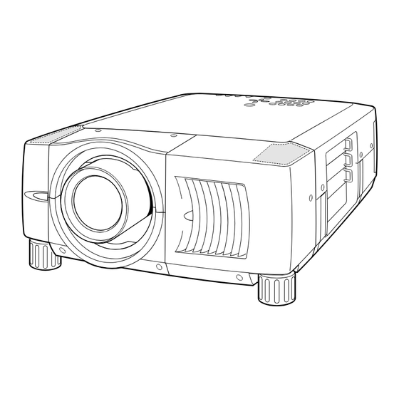
Multimedia Projector
(Combination of fan and filter-net has changed.)
Combination before change.
Combination after change.
Direction of exhaust.
Description
Part No.
Filter-net-B
--- --- ----
O/M-MV6A-A
610 299 6388
O/M-MV6A-D
610 299 6395
O/M-MV6A-F
610 299 6401
O/M-MV6A-I
610 299 6418
O/M-MV6A-E
610 299 6425
O/M-MV6AA
610 299 6791
O/M-MV6AA-D
610 299 6807
O/M-MV6AA-F
610 299 6814
O/M-MV6AA-I
610 299 6821
O/M-MV6AA-E
610 299 6838
O/M-MV6A-A
610 299 6388
After left lots.
After left lots.
After left lots.
CONTENTS ;
U.S.A. , Canada
Continental Europe, Asia, Africa, M.E.
U.K.
U.S.A. , Canada
U.S.A. , Canada
FILE NO.
MODEL NO.
Description
PLC-EF30
Delete.
O/M-MV6A-B
O/M-MV6A-D-A
Canada, Europe, Asia, Africa, M.E., U.K.
O/M-MV6A-F-A
O/M-MV6A-I-A
PLC-EF30N
O/M-MV6A-E-A
O/M-MV6AA-A
O/M-MV6AA-D-A
U.S.A., Canada
O/M-MV6AA-F-A
O/M-MV6AA-I-A
O/M-MV6AA-E-A
PLC-EF30L
O/M-MV6A-B
U.S.A.
Chassis No. MV6-EF3000
NOTE: Match the Chassis No. on the rating
sheet on the cabinet with the
Chassis No. in the Service Manual.
If the Original Version Service
Manual Chassis No. does not
match the unit's, additional
Service Literature is required. You
must refer to "Notices" to the
Original Service Manual prior to
servicing the unit.
Give complete "CHASSIS NO." for
parts order or servicing, it is shown on
the rating sheet on the cabinet of the
Projector.
2
3
4
6
9
13
18
33
35
43
49
53
55
60
63
66
S1~S10
B1~B2
P1~P5
(Projection lens is optional.)
(Projection lens is optional.)
MV6-EF30N00
MV6-EF30NL00
SM
REFERENCE NO.
5110304
Advertisement
Table of Contents

Related Manuals for Sanyo PLC-EF30


Summary of Contents for Sanyo PLC-EF30
-
Page 1: Service Manual
PLC-EF30 ■ Filter-net-B (Page-63 NO. 19 ) Delete. 610 292 3179 Filter-net-B --- --- ---- (Projection lens is optional.) ■ Owner's manual for PLC-EF30 only. 610 297 8025 O/M-MV6A-A 610 299 6388 O/M-MV6A-B 610 293 4977 O/M-MV6A-D 610 299 6395 O/M-MV6A-D-A Canada, Europe, Asia, Africa, M.E., U.K. -
Page 2: Technical Specifications
TECHNICAL SPECIFICATIONS Projector Type Multi-media Projector Dimensions (W x H x D) 17.3" x 9.1" x 23.8" (439 mm x 230 mm x 605.6 mm) LCD Panel System 1.8" TFT Active Matrix type, 3 panels Panel Resolution 1280 x 1024 dots Number of Pixels 3,932,160 (1,280 x 1,024 x 3 panels) Color System... -
Page 3: Safety Instructions
Safety Instructions PRODUCT SAFETY NOTICE SAFETY PRECAUTIONS Product safety should be considered when a compo- nent replacement is made in any area of the projec- tor. Components indicated by mark in the parts WARNING: list and the schematic diagram designate compo- The chassis of this projector is isolated (COLD) from nents in which safety can be of special significance. -
Page 4: Fuse For Circuit Protection
Protections This projector is equipped with the following protections to operate in safety. ❏ Fuse for circuit protection The fuse is located in the rear inside a projector. (Refer to figure.) When either the LAMP indicator or the READY indicator is not illuminated, fuse may be opened. -
Page 5: Overheating Protection
❏ Overheating Protection The temperature monitor system -- The temperature monitor system is provided to prevents damage of optical components (the LCD panel and polarization film etc.) inside a projector from overheat. Two protection systems are provided. Each system operation as follows ; ----- The temperature monitor -1: ----- --- The temperature monitor -2 : --- (Temperature check of lamps. -
Page 6: Lamp Replacement
LAMP REPLACEMENT Before Replacement This Projector is equipped with 2 Projection Lamps to ensure brighter image and those lamps are controlled by Lamp Management Function. Lamp Management Function detects status of two lamps and shows status on screen or on LAMP REPLACE indicator. - Page 7 Lamp Replacement CAUTION CAUTION For continued safety, replace with a lamp Do not drop a lamp assembly or touch a glass assembly of same type. bulb! Glass can shatter and may cause injury. Allow a projector to cool for at least 45 minutes before you open Lamp Cover.
- Page 8 Lamp counter reset Be sure to reset Lamp Counter when Lamp Assembly is replaced. When Lamp Replace Counter is reset, LAMP REPLACE indicator stops lighting. Turn projector on, press MENU button and ON-SCREEN MENU will appear. Press POINT LEFT/RIGHT button(s) to move a red frame pointer to SETTING Menu icon.
- Page 9 Mechanical disassemblies Black mark and clear tube Panel ballast and Lamp ballast or no mark and black tube. Assemblies removal. K7A3 Black color K7B3 White color 1. Remove 5 screws A and remove the Panel ballast. K7B4 2. Remove the connectors. Remove 8 screws B and remove the 2 Lamp ballast assemblies.
- Page 10 Lamp cover and cabinet top removal. 1. Turn 3 screws A and remove the Lamp cover. 2. Remove 8 screws B and remove the Cabinet top. Assembly main and Terminal slots unit removal. 1. Remove the connectors and the flexible cables of the LCD panels from the assembly Main.
- Page 11 Assembly Motor & audio, assembly Power, assembly PFC, assembly Sub power and Fan(FN902) Removal. NOTE : Be careful of the attachment direction of Fan. FN902 is Fan for an exhaust. FN902 : See the Production change notice of the cover. (Page-1) 1.
- Page 12 Fans(FN906, FN909 and FN910) removal. NOTE : Assembly fan Be careful of the attachment direction of Fan. FN906 is Fan for an exhaust. FN909 1. Remove 4 screws A and remove the fan FN909 and remove the fan FN910. 2. Remove 4 screws B and remove the assembly fan. 3.
-
Page 13: Optical Unit Disassemblies
Optical unit disassemblies Projection lens and Holder lens unit removal. 1. Turn 4 screws A and remove the Projection lens. 2. Remove 4 screws B and remove the Holder lens unit. Integrator lens in unit, Integrator lens out & PBS unit, Condenser lens unit, Relay lens unit and Polarizer units removal. - Page 14 Note : The characteristics and ages of lamps are managed by CPU. Mark the lamp assemblies as they are removed from the optical unit so that they may be reassembled in the same location from which they were Lamp assemblies and Assembly mirror removed.
- Page 15 Remove 4 screws and remove the prism / LCD panel assembly. At the time, be careful not to damage the prism / LCD panel assembly with the driver. Prism / LCD panel assembly removal. Caution : (1). Never touch the LCD panel and prism part directly with Note : hand.
-
Page 16: Optical Parts Location
Optical parts location --- The optical parts name(description) can see it on parts list(page65). 116(R) 117(G) 118(B) 119(R) 121(G) 122(B) 54 ( Without "89") 57 ( Without "88") (Bottom side) Blue NOTE : Set the direction of arrow marks in the output direction of the optics axis, about the lenses by which arrow marks were printed. - Page 17 PWB ASSEMBLIES LOCATION irection of a wind. MOTOR FANS LOCATION FN902 : See the Production change notice of the cover. (Page-1) -17-...
- Page 18 Troubleshooting NO PICTURE -1 ASS'Y MAIN TERMINAL BOARD DVI CHECK PSIG SIGNAL CHECK DATA IC6301 MEMORY SYNC SIGNAL IC6321 SGRAM IC6341 MEMORY IC2561 SGRAM IC2571 TO PRO. IC2581 TP-HV TP-32H1 SCAN TP-2561 MEMORY IC2591 CON- SGRAM TP-V TP-32V1 VERTER PSIG AUDIO PSIG1~4 INPUT...
- Page 19 NO PICTURE -2 Troubleshooting Check the terminal board-DVI. Check the Vcc voltages. S9V / -5V / S6V (Always) 9V / 5VB (Switched) Check the test points. DATA H_DIF H_DIF K80A Digital V_DIF V_DIF LATCH Interface DATA DE_DIF DE_DIF IC8001 CLK_DIF CLK_DIF TP-80R TP-80G...
-
Page 20: Timing Chart
Check the terminal board-AV. Check the Vcc voltages. S9V / -5V / S6V (Always) 9V / 5VB (Switched) Check the test points. ASS'Y AV TP-3142 BNC-Y IC1181C K131 IC2161B Y/C-Y IC1141B IC141B IC141C NTSC-Y BNC-Y C.V.-Y VIDEO-Y NTSC C.V. PAL-Y IC2161A YCbCr YCbCr... - Page 21 * NO POWER -1 System Control Troubleshooting Is fuse (F901) blown? Isn't the lamp cover Is the lamp cover attached Fuse may be opened of a projector correctly? And has not the when either the LAMP removed? boss(Inner side of the lamp indicator or the READY cover) broken? indicator isn't Illuminated.
- Page 22 * NO POWER-2 Troubleshooting Check the switching regulator. STR-Z2156 Switching regulator Caution : "HOT" Circuit ! If this Vcc voltage reaches to abnormal voltage (exceeds 22V), the IC632 will be shut down. If a temperature of this frame reaches to 150˚C, Check the signal at pin 5 the IC632 will be shut of T621.
-
Page 23: Audio System
No sound Troubleshooting Audio system Terminal board ASS'Y CGMOTHER - DVI ASS'Y_MAIN SLOT_1 K90C ASS'Y_RS232C K80H Terminal board - Component K38F K38E SLOT_2 K90D AUDIO_AMP. IC1871 K90K AUDIO_CONTROL K16B K10H L-OUT Terminal board R-OUT - AV SLOT_3 K90E IC001 K16F IC801 IC1851 K16A... -
Page 24: Lamp Abnormality
LAMP ABNORMALITY -1 System Control Troubleshooting NOTE : ■ The lamp emits light through arc discharge. To initiate arc discharge, dielectric breakdown must occur between the lamp electrodes. The high-voltage pulse generator generates and applies high- voltage pulses with peak values of about 20kV between the lamp electrodes in order to generate glow discharge. - Page 25 LAMP ABNORMALITY -2 Troubleshooting Check the unit P.F.C.. Has not the temperature switch operated? Check! If the temperature around Caution : "HOT" Circuit ! FET reaches 85 degrees, the PFC circuit will be shut down. OUTPUT DC 380V~400V Check! UNIT PFC U20B34600 LAMP CN1B...
-
Page 26: Power Lens System Abnormality
POWER LENS SYSTEM ABNORMALITY Troubleshooting Motor-driven lens system. (Zoom, Focus and lens shift.) LEFT DET. CENTER DET. Horizontal shift function does not exist RIGHT DET. in some particular models. Therefore IC1621, K8N, etc. do not exist in those models. K16A K16H TOP DET. -
Page 27: Temperature Abnormality
TEMPERATURE ABNORMALITY -1 Temperature sensors location can see it on "protections"( page-5). System Control Troubleshooting NOTE : Temperature monitor operation. TURE WARNING indicator at intervals of 0.6 seconds. Cooling fans operate until temperature ■ The temperature monitor system is provided to prevents damage of optical components (the returns to normal. - Page 28 TEMPERATURE ABNORMALITY -2 Troubleshooting Check the fan control circuit CHECK ! CHECK ! ● FAN DRIVE BUFFER ● OUTPUT ON/OFF SIGNAL From pin4 of IC6611 H : ON L : OFF VOLTAGE ● VOLTAGE CONTROL OUT CONTROL SIGNAL From IC6611 CHECK ! CHECK ! -32-...
- Page 29 Waveforms Timing chart 1 0 u s / D i v Terminal board-AV Video-in NTSC 0.5V/Div TP_32H1 H_sync 2V/Div TP_5101 0.5V/Div TP_5102 0.5V/Div TP_3141 C 0.5V/Div TP_3142 0.5V/Div TP_5181 TP_2301R 0.5V/Div 0 . 5 V / p _ p TP_201 TP_820R 0.5V/Div 0.5V/Div...
- Page 30 Timing chart 5 u s / D i v TP_2561 TP_2571 PSIG Red LCD panel drive signal 5V/Div Green LCD panel drive signal TP_2527 TP_2526 5V/Div 5V/Div Blue LCD panel drive signal 5V/Div 2 m s / D i v Input_signal NTSC 0.5V/Div TP_32V1...
-
Page 31: Alignment Procedures
Alignment procedures Service adjustment menu operation Normal Mode Service Mode ■ To enter the "service mode." "MENU" Service Mode "IMAGE" Group Data To enter the service mode, press the "MENU" and "IMAGE" buttons on the projector simultaneously and hold for 2 sec- "POWER onds. -
Page 32: Service Mode Adjustment Menu
■ Service mode adjustment Menu Adjustment Mode Adjustment Item Group-no. Not designated Component ● 140-0 Fans-A driving voltage adjustment ● 140-1 Fans-A driving voltage adjustment ● 140-2 Fans-C driving voltage adjustment ● 140-3 Fans-C driving voltage adjustment ● 140-4 Fans-B driving voltage adjustment ●... -
Page 33: Adjustment Mode
Adjustment Mode Adjustment Item Group-no. Not designated Component ● 210-14 & 16 AV White balance adjustment. 2 lamp mode ● 200-14 & 16 PC White balance adjustment. 2 lamp mode ● 211-14 & 16 AV White balance adjustment. Lamp-1 of 1 lamp mode ●... -
Page 34: Electrical Adjustments
■ Electrical adjustments 1. Voltage adjustment Note : Equipment Digital voltmeter ■ The following adjustment is the adjustment item for Assembly power. Connections + K6D(2) - chassis ground The test point exists on the Assembly power. Voltage adjustment. Adjustment: Adjust the voltage of K6D to 6.35± 0.05V DC with the VR652. ■... - Page 35 3. The voltage check of the 3D-Noise-reduction-PLL circuit. 5. Component Video signal adjustments Equipment Digital voltmeter Connections : + TP5103/ - chassis ground. Equipment Oscilloscope. Input mode Input mode Y, Cb, Cr. Input signal Color bar signal(PAL) Input signal 16 step gray scale signal Picture condition Normal Picture condition...
- Page 36 6. Fan driving voltage adjustments 9. Pedestal level adjustments -PC Equipment Digital voltmeter. Equipment Oscilloscope. Input mode Computer. Set the image to "Service mode." Input signal 16 step gray scale signal Adjust each item for below values with the Volume + and - buttons. Set the image to "Service mode."...
-
Page 37: Black Level
11. Pedestal level adjustments AV 13. Panel driving signal adjustments -AV Equipment Oscilloscope. Equipment Oscilloscope. Input mode Input mode Input signal 16 step gray scale signal Input signal 16 step gray scale signal Set the image to "Service mode." Picture condition Normal. - Page 38 15. Flicker reduction Input mode Computer. Input signal 1 dot line computer signal Set the image to "Service mode." Adjust each color for minimum flickers with the Volume + - buttons. Group Screen 200- Display only green light. 200- Display only red light. 200- Display only blue light.
-
Page 39: Before Adjustment
Optical components adjustments Polarizer adjustment Relay lens adjustment Integrator lens out adjustment Focus of Polarizer LCD panel adjustment adjustment Polarizer adjustment Condenser lens Prism PBS adjustment adjustment Integrator lens in ■ Adjustment optical components location adjustment ■ Before Adjustment 1. Each adjustment requires ball allen wrenches set and slot screwdrivers set. 2. - Page 40 ■ Focus of LCD Panel Adjustment SCREW-A SCREW-A SLOT-B Prism / LCD Panel assembly SCREW-A SCREW-A Before Adjustment : 1. Turn on a projector. 2. Set the image to "service mode" and project a green grid pattern on a screen. And adjust green grid pattern to sharp focus, pressing Focus(▲)(▼) buttons on the projector or remote control unit.
- Page 41 ■ Integrator-lens-in adjustment-1 Before Adjustment : * Remove the flexible cables of LCD panels from SLOT-B SCREW-A the assembly Main. And turn on the projector. * Shift the adjustment position of Integrator-lens- out temporarily until shade appears the right or the left on the screen.
- Page 42 ■ Integrator-lens-in adjustment-2 SCREW-A SCREW-B SCREW-A Before Adjustment : 1. Remove the flexible cables of LCD panels from the assembly Main. And turn on the projector. 2. Insert light block sheets in front of the Red and Blue panels to block the red and blue lights so that green light is project- 3.
- Page 43 ■ Condenser-lens adjustment Before Adjustment : 1. Remove the connector K8E and connector K8V, and remove the flexible cables of LCD panels from the SLOT-B assembly Main. And turn on the projector. SLOT-B 2. Insert light block sheet in front of the blue panel to block the blue light so that yellow light is pro- (Green and Red lights)
- Page 44 ■ Prism P.B.S. adjustment Adjustment : 1. Remove the flexible cables of LCD panels from the SLOT-A assembly Main. And turn on the projector. 2. Loosen two screws-B. SCREW-B 3. Insert a slot screwdriver into slot-A, turn it and adjust the center position of screen to maximum brightness.
- Page 45 CPU and I/O-Expander Control port functions CPU (IC801 144 pin) Control port functions Name Function Name Function Polarity Pin No. PA23/WRHH USB RESET USB Reset signal Active L PE14/TIOC4C/DACK0/AH PA22/WRHL PA21/CASHH RS232C_SW RS232C Output select signal PE15/TIOC4D/DACK1/IRQOUT POWER SW "L":Power OFF "H":Power ON PC0/A0 ADDRESS0 Address Bus 0...
- Page 46 CPU and I/O-Expander Control port functions Name Function Name Function Polarity Pin No. PD16/D16/IRQ0 PW_PG_SEL PW365 232C Write SW(SH="H",PIXEL="L") PD15/D15 DATA15 Data Bus 15 PD14/D14 DATA14 Data Bus 14 PD13/D13 DATA13 Data Bus 13 PD12/D12 DATA12 Data Bus 12 PD11/D11 DATA11 Data Bus 11 PD10/D10...
- Page 47 CPU and I/O-Expander Control port functions I/O Expander Control port functions (IC1801 64 pin) Y / V Name Function Name Function Polarity Pin No. BLAST_SW3 Lamp Ballast 1 On/Off SW * ON = H BLAST_SW4 Lamp Ballast 2 On/Off SW * ON = H 5V ±10% LENS_UP...
- Page 48 CPU and I/O-Expander Control port functions Output Expander Control port functions (IC1822 20 pin) Name Function Name Function Polarity Pin No. EXP_RST SCONFIG Single to Dual converter Enhancer CONFIG Signal Data Bus 0 Data Bus 1 IP_RESET IP_RESET PROGRAM PROGRAM Data Bus 2 Data Bus 3 USB_BRST...
-
Page 49: The Cautions In Schematic Diagrams
The cautions in schematic diagrams ■ 1. PRODUCT SAFETY NOTICE COMPONENTS DESIGNATED BY A MARK ( ) IN THIS SCHEMATIC DIAGRAM DESIGNATE COMPONENTS WHOSE VALUES ARE OF SPECIAL SIGNIFICANCE TO PRODUCT SAFETY. SHOULD ANY COMPONENT DESIGNATED BY A MARK NEED TO BE REPLACED, USE ONLY THE PART DESIGNATED IN THE PARTS LIST. - Page 50 The cautions in schematic diagrams Read description in the Capacitor and Resister as follows: CAPACITOR 16 K K 0.47 BA Characteristic Rated value Tolerance Symbols Static capacitance of 10PF or less Material : Nondesignated ±0.1PF CERAMIC Temperature compensating ceramic ±0.25PF CERAMIC High dielectric rate ceramic ±0.5PF...
- Page 51 UNIT P.F.C., UNIT LAMP BALLAST and IC BLOCK DIAGRAMS UNIT P.F.C. OUTPUT DC 380V~400V UNIT PFC U20B34600 LAMP CN1B BALLAST-1 CN3B PFC-1 AC-INPUT AC 90V~264V BALLAST-1 ON/OFF CONTROL LAMP-1 MONITOR TEMP. SW 85˚C LAMP BALLAST-2 CN4B PFC-2 TEMP. SW 12V (+B) BALLAST-2 ON/OFF RL12 CONTROL...
- Page 52 STR-Z2156 Switching regulator G (H) T621 D655 PROTECTION ABNORMAL ABNORMAL START TEMP. DET. VOL. DET. D651 DELAY LATCH LOGIC D652 OC-RC CONTROL 6.25V CONT G (L) VOLTAGE CONTROL PC611 IC652 PC612 ABNORMAL VOLTAGE DETECT <FF> FA7612CN PWM POWER CONTROL ON/OFF ●...
- Page 53 LB1641/1645N MOTOR DRIVER LB1645N LB1641 INPUT ON/OFF CONTROL INPUT S1=ON , OTHER=OFF FORWARD (reverse) DRIVE S2=ON , OTHER=OFF REVERSE (forward) DRIVE S3=ON , OTHER=OFF BRAKING <FF> MPXA4115A SMALL OUTLINE Pressure sensor for altimeter PACKAGE PPXA4115A CASE 482–01 <FF> FLUORO SILICONE STAINLESS GEL DIE COAT STEEL CAP...
- Page 54 CXD3511Q DIGITAL SIGNAL DRIVER DSD BLOCK DATA BUS USER USER R, G, B, IN SWITCH GAIN BRIGHT GAIN BRIGHT GAIN YS, YM, R, G, B, OSD UNEVEN PATTERN GAMMA MUTE 1 COLOR BRIGHT GENERATOR CORRECTION CORRECTION POST POST CYCLE DELAY MUTE 2 LIMITER GAIN...
- Page 55 CXA3562R LCD DRIVER <FF> -59-...
-
Page 56: Parts List
Parts list ■ PRODUCT SAFETY NOTICE Product safety should be considered when a component replacement is made in any Note: area of a Projector. Components indicated by a mark in this parts list and the Part order must contain Chassis No., Part schematic diagram show components whose value have special significance to product No., and descriptions. - Page 57 Read description in the Capacitor and Resister as follows: CAPACITOR CERAMIC 100P K 50V Rated Voltage Tolerance Symbols Rated value: P=Pico farad, U=Micro farad Static capacitance of 10PF or less Nondesignated Material : ±0.1PF CERAMIC Temperature compensating ceramic ±0.25PF ±0.5PF High dielectric rate ceramic ±1PF Semiconductor ceramic...
- Page 58 PWB ASSEMBLIES LOCATION irection of a wind. MOTOR FANS LOCATION FN902 : See the Production change notice of the cover. (Page-1) -62-...
- Page 59 Refer to lens instruction manual. 126A Cabinet Chassis -63-...
- Page 60 116(R) 117(G) 118(B) 119(R) 121(G) 122(B) 54 ( Without "89") 57 ( Without "88") (Bottom side) Blue NOTE : Set the direction of arrow marks in the output direction of the optics axis, about the lenses by which arrow marks were printed. (Refer to figure.) Axis Light souse...
- Page 61 STAND LEG CT-MJ6A 123. 645 046 1446 DICHROIC MIRROR (C) 610 272 9238 SPRING COIL-M6MA 124. 645 050 4105 DICHROIC MIRROR (Y/IA) 645 032 6400 BADGE,SANYO*43.5X10L43.5 128. 610 296 8231 ASSY,LCD PNL/PRISM-MV6A ****************************************************** ************************** For model PLC-EF30N Only CHASSIS PARTS 006MV6A 126.
- Page 62 Electrical Parts List Ref. No. Part No. Description Ref. No. Part No. Description 405 147 2205 TR 2SA1037AK-S-T146 ****************************************************************** 405 002 0308 TR 2SA1037K T146 R Out of PWB Assembly 405 002 0407 TR 2SA1037K T146 S 405 002 6706 TR 2SA1179-M6-TB COIL 405 002 6904...
- Page 63 Electrical Parts List Ref. No. Part No. Description Ref. No. Part No. Description 405 163 1602 TR 2SC2812N-L6-TB0 405 014 4608 TR 2SC2412K T146 S 405 163 1701 TR 2SC2812N-L7-TB0 405 015 8704 TR 2SC2812-L6-TB Q2101 405 134 5905 TR 2SA1037AK-T146-R 405 015 8902 TR 2SC2812-L7-TB 405 147 2205...
- Page 64 Electrical Parts List Ref. No. Part No. Description Ref. No. Part No. Description C1101 403 145 9905 CERAMIC 22P J C2150 403 164 0204 CERAMIC 0.1U Z C1102 403 145 9905 CERAMIC 22P J C2151 403 164 0204 CERAMIC 0.1U Z C1103 403 164 0204 CERAMIC...
- Page 65 Electrical Parts List Ref. No. Part No. Description Ref. No. Part No. Description C4172 403 215 2201 CERAMIC 0.01U K R1149 401 105 0405 MT-GLAZE 100 JA 1/16W C4181 403 164 0204 CERAMIC 0.1U Z R1151 401 105 0405 MT-GLAZE 100 JA 1/16W C4182 403 283 6309...
- Page 66 Electrical Parts List Ref. No. Part No. Description Ref. No. Part No. Description R2121 401 105 0603 MT-GLAZE 10K JA 1/16W R3190 401 105 4007 MT-GLAZE 330 JA 1/16W R2122 401 105 0900 MT-GLAZE 120 JA 1/16W R3191 401 105 0405 MT-GLAZE 100 JA 1/16W R2123...
- Page 67 Electrical Parts List Ref. No. Part No. Description Ref. No. Part No. Description L1151 645 044 3626 FILTER,LP 7MHZ 405 015 8704 TR 2SC2812-L6-TB L1161 645 044 3626 FILTER,LP 7MHZ 405 015 8902 TR 2SC2812-L7-TB L1162 645 021 1607 INDUCTOR,10U J 405 163 1602 TR 2SC2812N-L6-TB0 L121...
- Page 68 Electrical Parts List Ref. No. Part No. Description Ref. No. Part No. Description IC3273 410 401 7506 IC TC74VCX16374FT C1341 403 149 9208 CERAMIC 0.01U Z IC3274 410 321 8300 IC TC74VCX16244FT C1351 403 280 0508 ELECT 470U M IC3275 410 401 7506 IC TC74VCX16374FT C1352...
- Page 69 Electrical Parts List Ref. No. Part No. Description Ref. No. Part No. Description C2419 403 164 0204 CERAMIC 0.1U Z C3276 403 164 0204 CERAMIC 0.1U Z C2421 403 164 0204 CERAMIC 0.1U Z C3277 403 113 3805 CERAMIC 1000P K C2423 403 164 0204 CERAMIC...
- Page 70 Electrical Parts List Ref. No. Part No. Description Ref. No. Part No. Description C440 403 348 5803 CERAMIC 0.47U K C6341 403 164 0204 CERAMIC 0.1U Z C445 403 164 0204 CERAMIC 0.1U Z C6343 403 164 0204 CERAMIC 0.1U Z C446 403 164 0204 CERAMIC...
- Page 71 Electrical Parts List Ref. No. Part No. Description Ref. No. Part No. Description 645 028 5981 R-NETWORK 10X4 1/16W R1371 401 105 0405 MT-GLAZE 100 JA 1/16W RB2516 645 037 3107 R-NETWORK 10X4 0.063W R1372 401 105 0405 MT-GLAZE 100 JA 1/16W 645 028 5981 R-NETWORK 10X4 1/16W R1373...
- Page 72 Electrical Parts List Ref. No. Part No. Description Ref. No. Part No. Description R2311 401 037 5004 MT-GLAZE 0.000 ZA 1/10W R2483 401 105 7909 MT-GLAZE 0.000 ZA 1/16W R2312 401 037 5004 MT-GLAZE 0.000 ZA 1/10W R2484 401 105 7909 MT-GLAZE 0.000 ZA 1/16W R2313...
- Page 73 Electrical Parts List Ref. No. Part No. Description Ref. No. Part No. Description R3274 401 105 7909 MT-GLAZE 0.000 ZA 1/16W R3450 401 105 7909 MT-GLAZE 0.000 ZA 1/16W R3275 401 105 7909 MT-GLAZE 0.000 ZA 1/16W R3451 401 105 7909 MT-GLAZE 0.000 ZA 1/16W R3278...
- Page 74 Electrical Parts List Ref. No. Part No. Description Ref. No. Part No. Description R3611 401 105 5301 MT-GLAZE 4.7K JA 1/16W R488 401 105 7909 MT-GLAZE 0.000 ZA 1/16W R3612 401 105 5400 MT-GLAZE 47K JA 1/16W R4881 401 035 4108 MT-GLAZE 0.000 ZA 1/8W...
- Page 75 Electrical Parts List Ref. No. Part No. Description Ref. No. Part No. Description R5836 645 030 1056 PROTECTOR,IC 3.8A 72V R7367 401 105 2607 MT-GLAZE 22 JA 1/16W R5837 401 105 7404 MT-GLAZE 8.2K JA 1/16W R7368 401 105 2607 MT-GLAZE 22 JA 1/16W R5838...
- Page 76 Electrical Parts List Ref. No. Part No. Description Ref. No. Part No. Description R8275 401 105 0306 MT-GLAZE 10 JA 1/16W L3351 645 026 1008 INDUCTOR,3.3U M R8280 401 105 0603 MT-GLAZE 10K JA 1/16W L3521 645 026 1008 INDUCTOR,3.3U M R8281 401 105 7909 MT-GLAZE...
- Page 77 Electrical Parts List Ref. No. Part No. Description Ref. No. Part No. Description TP32H1 645 036 5010 TERMINAL R600 401 008 8607 CARBON 220K JA 1/2W TP32H2 645 036 5010 TERMINAL R601 402 078 5701 WIRE WOUND 3.9 JA TP32V1 645 036 5010 TERMINAL R605...
- Page 78 Electrical Parts List Ref. No. Part No. Description Ref. No. Part No. Description 405 015 8704 TR 2SC2812-L6-TB C6647 403 149 1400 ELECT 33U M 405 015 8902 TR 2SC2812-L7-TB C6648 403 164 0204 CERAMIC 0.1U Z 405 163 1602 TR 2SC2812N-L6-TB0 C6649 403 149 1400...
- Page 79 Electrical Parts List Ref. No. Part No. Description Ref. No. Part No. Description R7617 401 105 0603 MT-GLAZE 10K JA 1/16W D2694 407 149 0807 DIODE 1SS355-TE-17 R7618 401 105 0603 MT-GLAZE 10K JA 1/16W D2695 407 149 0807 DIODE 1SS355-TE-17 R7625 401 105 2904 MT-GLAZE...
- Page 80 Electrical Parts List Ref. No. Part No. Description Ref. No. Part No. Description Q9016 405 047 9007 TR 2SB1204-S-TL C9062 403 280 1604 ELECT 220U M Q9017 405 014 4509 TR 2SC2412K T146 R C9063 403 280 1604 ELECT 220U M 405 014 4608 TR 2SC2412K T146 S C9064...
- Page 81 Electrical Parts List Ref. No. Part No. Description Ref. No. Part No. Description R9085 401 226 1206 MT-GLAZE 150 FA 1/16W L9004 645 026 1008 INDUCTOR,3.3U M R9086 401 105 0405 MT-GLAZE 100 JA 1/16W L9005 645 026 1008 INDUCTOR,3.3U M R9087 401 226 1206 MT-GLAZE...
- Page 82 Electrical Parts List Ref. No. Part No. Description Ref. No. Part No. Description C1653 403 343 4900 ELECT 470U M R6828 401 105 3307 MT-GLAZE 2.7K JA 1/16W C1654 403 215 2201 CERAMIC 0.01U K R6829 401 105 2003 MT-GLAZE 1.8K JA 1/16W C1656 403 343 4900...
- Page 83 Electrical Parts List Ref. No. Part No. Description Ref. No. Part No. Description DIODE R6868 401 105 2805 MT-GLAZE 2.2K JA 1/16W D3851 407 223 0501 ZENER DIODE 02DZ12Y(TPH3) DIODE D3852 407 223 0501 ZENER DIODE 02DZ12Y(TPH3) D6851 407 196 9907 LED SEL4828A D3853 407 223 0501...
- Page 84 Electrical Parts List Ref. No. Part No. Description Ref. No. Part No. Description Q8091 405 014 4509 TR 2SC2412K T146 R C8063 403 164 0204 CERAMIC 0.1U Z 405 014 4608 TR 2SC2412K T146 S C8064 403 157 1904 CERAMIC 10P D 405 015 8704 TR 2SC2812-L6-TB...
- Page 85 Electrical Parts List Ref. No. Part No. Description Ref. No. Part No. Description R8018 401 105 5103 MT-GLAZE 47 JA 1/16W R8172 401 105 7909 MT-GLAZE 0.000 ZA 1/16W R8019 401 105 7909 MT-GLAZE 0.000 ZA 1/16W R8173 401 105 7909 MT-GLAZE 0.000 ZA 1/16W R8021...
- Page 86 Electrical Parts List Ref. No. Part No. Description Ref. No. Part No. Description IC1053 410 343 7008 IC SN74AHCT1G14DBVR ****************************************************************** IC1061 409 502 8703 IC TA1318N PWB assembly for TERMINAL BOARD COMPONENT IC2001 409 449 2802 IC AN5393FBQ IC2041 409 461 7809 IC PQ20WZ11 IC2061 409 051 2900...
- Page 87 Electrical Parts List Ref. No. Part No. Description Ref. No. Part No. Description C2054 403 215 2201 CERAMIC 0.01U K R1064 401 113 5201 MT-GLAZE 360 JA 1/16W C2055 403 215 2201 CERAMIC 0.01U K R1065 401 105 0405 MT-GLAZE 100 JA 1/16W C2056 403 215 2201...
- Page 88 Electrical Parts List Ref. No. Part No. Description Ref. No. Part No. Description R3009 401 105 3000 MT-GLAZE 220K JA 1/16W K10C 645 041 1076 SOCKET,DIN 8P R3011 401 105 3000 MT-GLAZE 220K JA 1/16W K10H 645 041 6071 SOCKET,I/O 176P R3012 401 105 0405 MT-GLAZE...
- Page 89 610 234 0969 CABLE 610 299 7248 COMPL,COVER LENS B-MV6K (including "*") ******************************************************** 610 290 9258 COVER LNS B-MV6A ACCESSORIES FOR PLC-EF30 ONLY. (009MV6A) 610 293 8937 COVER LNS C-MV6A 610 299 6302 COVER LENS E-MV6A 645 015 3976 CABLE,FXAF...
- Page 90 Memo...
- Page 91 Memo...
- Page 92 Feb./ 2002 Printed in Japan SANYO Electric Co., Ltd...
Need help?
Do you have a question about the PLC-EF30 and is the answer not in the manual?
Questions and answers