Table of Contents
Advertisement
18.5" LCD Color Monitor
Service
Service
Service
Description
Table Of Contents..........................................................1
Revision List..................................................................2
Important Safety Notice................................................3
1. Monitor Specifications.................................................4
2. LCD Monitor Description........................................5
3. Operation Instructions...............................................6
3.1 Control Buttons......................................................6
3.2 Attaching the Cables...............................................7
3.3 Adjusting the Picture..................................................7
4. Input/Output Specification.......................................10
4.1 Input Signal Connector...........................................10
N
4.2 Factory Preset Display Modes..................................10
4.3 Panel Specification................................................11
5. Block Diagram........................................................13
5.1 Software Flow Chart............................................13
ANY PERSON ATTEMPTING TO SERVICE THIS CHASSIS MUST FAMILIARIZE HIMSELF WITH THE
CHASSIS AND BE AWARE OF THE NECESSARY SAFETY PRECAUTIONS TO BE USED WHEN SERVICING
ELECTRONIC EQUIPMENT CONTAINING HIGH VOLTAGES.
CAUTION: USE A SEPARATE ISOLATION TRANSFOMER FOR THIS UNIT WHEN SERVICING
TABLE OF CONTENTS
Page
Description
5.2 Electrical Block Diagram...................................15
6.Schematic.............................................................17
6.1 Main Board..........................................................17
6.2 Power Board.......................................................22
6.3 Key Board.........................................................25
7.PCB Layout...........................................................26
7.1 Main Board.........................................................26
7.2 Power Board.......................................................28
7.3 Key Board...........................................................29
8. Maintainability........................................................30
8.1 Equipments and Tools Requirement....................30
8.2 Trouble Shooting................................................30
9. White-Balance, Luminance adjustment...................36
10. Monitor Exploded View.....................................38
11. BOM List..............................................................39
SAFETY NOTICE
1
HCL HCMELWBT11
Horizontal Frequency
31kHz - 80kHz
Page
Advertisement
Table of Contents

Related Manuals for HCL HCL HCMELWBT11


Summary of Contents for HCL HCL HCMELWBT11
-
Page 1: Table Of Contents
18.5” LCD Color Monitor HCL HCMELWBT11 Service Service Service Horizontal Frequency 31kHz – 80kHz TABLE OF CONTENTS Description Page Description Page 5.2 Electrical Block Diagram….…...………..…..…...15 Table Of Contents..……..……......…..1 6.Schematic……………...........…17 Revision List.….....…….......……..2 6.1 Main Board.……...……..........17 Important Safety Notice.………….......……..3 6.2 Power Board..………..……........22 1. -
Page 2: Revision List
18.5” LCD Color Monitor HCL HCMELWBT11 Revision List Revision Date Revision History TPV Model Apr.-1-09 Initial Release T8RCM5DCXXKLAN... -
Page 3: Important Safety Notice
18.5” LCD Color Monitor HCL HCMELWBT11 Important Safety Notice Proper service and repair is important to the safe, reliable operation of all AOC Company Equipment. The service procedures recommended by AOC and described in this service manual are effective methods of performing service operations. -
Page 4: Monitor Specifications
18.5” LCD Color Monitor HCL HCMELWBT11 1. Monitor Specifications Driving system 18.5” TFT Color LCD Size 47.0cm LCD Panel Pixel pitch 0.3mm( H )x0.3mm( V ) Video R,G,B Analog Interface Input H-Frequency 31KHz – 80KHz V-Frequency 55-75Hz Display Colors 16.7M Colors Dot Clock 85.5MHz... -
Page 5: Lcd Monitor Description
18.5” LCD Color Monitor HCL HCMELWBT11 2. LCD Monitor Description The LCD monitor will contain a main board, a power board and a key board which house the flat panel control logic, brightness control logic and DDC. The power board will provide AC to DC Inverter voltage to drive the backlight of panel and the main board chips each voltage. -
Page 6: Operation Instructions
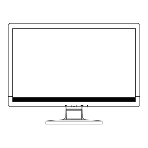
18.5” LCD Color Monitor HCL HCMELWBT11 3. Operating Instructions General Instructions Press the power button to turn the monitor on or off. The other control buttons are located at front panel of the monitor. By changing these settings, the picture can be adjusted to your personal preferences. -
Page 7: Attaching The Cables
18.5” LCD Color Monitor HCL HCMELWBT11 • Auto Adjust button / Exit: 1. When OSD menu is in active status, this button will act as EXIT-KEY (EXIT OSD menu). 2. When OSD menu is in off status, press this button for 2 seconds to activate the Auto Adjustment function. - Page 8 18.5” LCD Color Monitor HCL HCMELWBT11 The OSD Message Main Main Menu Sub Menu Sub Menu Menu Description Item Item Icon Icon Brightness Backlight Adjustment Contrast Contrast from Digital-register. Standard Standard Mode Text Text Mode Internet Internet Mode Game Game Mode...
- Page 9 18.5” LCD Color Monitor HCL HCMELWBT11 Main Main Menu Sub Menu Sub Menu Menu Description Item Item Icon Icon Warm Recall Warm Color Temperature from EEPROM. Normal Recall Normal Color Temperature from EEPROM. Cool Recall Cool Color Temperature from EEPROM.
-
Page 10: Input/Output Specification
18.5” LCD Color Monitor HCL HCMELWBT11 4. Input/Output Specification 4.1 Input Signal Connector Pin No. Description Pin No. Description Green Logic Ground Blue Monitor Ground Monitor Ground DDC-Serial Data DDC-return H-Sync R-Ground V-Sync G-Ground DDC-Serial Clock B-Ground 15 - Pin Color Display Signal Cable 4.2 Factory Preset Display Modes... -
Page 11: Panel Specification
18.5” LCD Color Monitor HCL HCMELWBT11 4.3 Panel Specification CLAA185WA02 is 18.51” color TFT-LCD (Thin Film Transistor Liquid Crystal Display) module composed of LCD panel, driver ICs, control circuit and backlight. By applying 6bit+Hi-FRC digital data, 1366*768, 16.7M-color images are displayed on the 18.51” diagonal screen. Input power voltage is 5.0V for LCD driving. Inverter for backlight is not included in this module. - Page 12 18.5” LCD Color Monitor HCL HCMELWBT11 4.3.3 Electrical Characteristics TFT LCD Module: Back Light Unit: • Electrical Specification • Lamp Life Time...
-
Page 13: Block Diagram
18.5” LCD Color Monitor HCL HCMELWBT11 5. Block Diagram 5.1 Software Flow Chart... - Page 14 18.5” LCD Color Monitor HCL HCMELWBT11 Remark: 1) MCU initializes. 2) Is the EPROM blank? 3) Program the EPROM by default values. 4) Get the PWM value of brightness from EPROM. 5) Is the power key pressed? 6) Clear all global flags.
-
Page 15: Electrical Block Diagram
18.5” LCD Color Monitor HCL HCMELWBT11 5.2 Electrical Block Diagram 5.2.1 Main Board Panel Interface Crystal 14.318MHZ (CN403) (X401) Scalar TSUM1PFR FLASH ROM Key Control SST25LF020A (Include ADC, OSD, MCU) Interface (U402) (CN401) (U401) D-Sub Connector (CN101) - Page 16 18.5” LCD Color Monitor HCL HCMELWBT11 5.2.2 Power Board AC input Bridge Rectifier EMI filter Transformer Rectifier diodes and Filter Start Resistor R904, R932, R933 Feedback PWM Control Circuit Power Switch (IC901) (Q901) Photocoupler (IC902) Output Transformer MOSFET (T801) (Q802)
-
Page 17: Schematic
18.5” LCD Color Monitor HCL HCMELWBT11 6. Schematic 6.1 Main Board 715G2904 2 2 TSUM1PFR-LF SCHEMATIC XGA/SXGA LVDS OUTPUT DSUB_R+ DSUB_R+ VCC1.8 DSUB_R- DSUB_R- DSUB_G+ DSUB_G+ VCC3.3 DSUB_G- DSUB_G- VCC1.8 DSUB_SOG DSUB_SOG CMVCC DSUB_B+ DSUB_B+ DSUB_5V DSUB_B- DSUB_B- VCC3.3 CMVCC1... - Page 18 18.5” LCD Color Monitor HCL HCMELWBT11 H_Sy nc R101 0R05 1/10W 5% R102 100R 1/16W 5% DSUB_H V_Sy nc R103 100R 1/16W 5% FB102 DSUB_V R104 C101 VGA_B+ DSUB_B+ VCC3.3 R105 R106 C102 C103 BEAD 2K2 1/16W 5% 2K2 1/16W 5% 100R 1/16W 5% 0.047uF...
- Page 19 18.5” LCD Color Monitor HCL HCMELWBT11 AVDD VDDP VDDC VCC3.3 VDDP AVDD FB401 U401 VCC3.3 300OHM VCTRL VCTRL C403 C404 LVA3P 0.1uF/16V 0.1uF/16V DSUB_R+ RIN0P LVA3M DSUB_R- RIN0M PA[0..1] DSUB_G+ GIN0P PA[0..1] DSUB_G- GIN0M LVA2P DSUB_SOG SOGIN0 LVA2M DSUB_B+ BIN0P...
- Page 20 18.5” LCD Color Monitor HCL HCMELWBT11 CN403 PA[0..1] PB[0..9] PA[0..1] PB[0..9] LVB0P LVB0M LVB1P LVB1M LVB2P LVB2M LVBCKP LVBCKM PA[4..9] LVB3P LVB3M PA[4..9] CONN VCC3.3 CMVCC R438 R443 PANEL_VCC 0R05 1/16W NC/0ohm AO3401L R434 C420 R433 R461 C419 330 OHM 1/4W 0.1uF/16V...
- Page 21 18.5” LCD Color Monitor HCL HCMELWBT11 ESD_5V ESD_5V DSUB_5V DSUB_5V 5 CMVCC D403 D401 5, 6 CMVCC NC/BAT54C BAV99 VCC3.3 VCC3.3 CN404 VCC3.3 R437 R439 CMVCC1 SM340A D402 10K 1/16W 5% 10K 1/16W 5% CMVCC CMVCC1 CMVCC BKLT-EN VCC1.8 Q410...
-
Page 22: Power Board
18.5” LCD Color Monitor HCL HCMELWBT11 6.2 Power Board 715G2852 2 R918 100 OHM 1/4W L904 R919 +12V 1.0uH 100 OHM 1/4W C912 ZD902 0.001uF C930 RLZ13B R920 C922 R946 100 OHM 1/4W 470UF/25V 150 OHM 2W 0.1uF C917 C918... - Page 23 18.5” LCD Color Monitor HCL HCMELWBT11 CONN C839 T801 R821 1500PF/50V POWER X'FMR R817 1K 1/8W 10K 1/10W 1% CN801 R855 D805 15R 1/4W LL4148 C819 C801 F801 0.0022uF 30pF/3KV +12V 0 OHM 1/4W C802 R804 Q801 470UF/25V C824 R856...
- Page 24 18.5” LCD Color Monitor HCL HCMELWBT11 +5V1 R602 10K 1/10W 5% C604 100uF/25V R603 10K 1/10W 5% C609 1uF/25V R601 10K 1/10W 5% CONN MUTE IC601 LOUT- SE/BTL LOUT- CN601 VOLUME LOUT+ R604 10K 1/10W 5% C601 0.47uF/16V LIN- LOUT+...
-
Page 25: Key Board
18.5” LCD Color Monitor HCL HCMELWBT11 6.3 Key Board 715G2835 1 LED_GRN# LED_Y EL# LED001 CN001 LBADC1 R002 2K OHM 1/4W LBADC2 DC_POWERON R003 0R05 1/10W 1% LED_YEL# LED_GRN# C001 C002 C003 C004 C005 R004 2K OHM 1/4W R005 1K 1/10W 1% NC/0.001uF... -
Page 26: Pcb Layout
18.5” LCD Color Monitor HCL HCMELWBT11 7. PCB Layout 7.1 Main Board 715G2904 2 2... - Page 27 18.5” LCD Color Monitor HCL HCMELWBT11...
-
Page 28: Power Board
18.5” LCD Color Monitor HCL HCMELWBT11 7.2 Power Board 715G2852 2... -
Page 29: Key Board
18.5” LCD Color Monitor HCL HCMELWBT11 7.3 Key Board 715G2835 1... -
Page 30: Maintainability
18.5” LCD Color Monitor HCL HCMELWBT11 8. Maintainability 8.1 Equipments and Tools Requirement Voltmeter. Oscilloscope. Pattern Generator. DDC Tool with an IBM Compatible Computer. Alignment Tool. LCD Color Analyzer. Service Manual. User Manual. 8.2 Trouble Shooting 8.2.1 Main Board No power... - Page 31 18.5” LCD Color Monitor HCL HCMELWBT11 No picture (LED orange) No picture The button if under X401 oscillate Replace X401 waveform is normal control Check reset circuit of Check Correspondent component U401 is normal Check C423(+) =1.8V; U404 Vout=3.3V Replace U401...
- Page 32 18.5” LCD Color Monitor HCL HCMELWBT11 White screen White screen Measure Q404 base X401 oscillate waveform is normal is low level? Replace X401 Check CN403 is solder Check reset circuit of and Q405 is OK U401 is normal Check Correspondent Check Correspondent component.
- Page 33 18.5” LCD Color Monitor HCL HCMELWBT11 8.2.2 Power Board No power Check AC line volt 110V or 220V Check AC input Check the voltage of C907 (+) Check bridge rectified circuit and F901 circuit Check start voltage for the pin3 of IC901...
- Page 34 18.5” LCD Color Monitor HCL HCMELWBT11 No backlight Check C802=12V Check adapter and F801 Check ON/OFF signal Check main board Check IC801 PIN12=12V Change ON/OFF circuit Check IC801 PIN5 have triangle wave Change IC801 Check IC801 PIN9/PIN10 PWM wave Check IC801...
- Page 35 18.5” LCD Color Monitor HCL HCMELWBT11 8.2.3 Key Board OSD is unstable or not working Connect Key Pad Board Is Key Pad Board connecting normally? Replace Button Switch Is Button Switch normally? Is Key Pad Board Normally? Replace Key Pad Board...
-
Page 36: White-Balance, Luminance Adjustment
18.5” LCD Color Monitor HCL HCMELWBT11 9. White-Balance, Luminance Adjustment Approximately 30 minutes should be allowed for warm up before proceeding White-Balance adjustment. 1. How to do the Chroma-7120 MEM. Channel setting A. Reference to chroma 7120 user guide B. Use “SC” key and “NEXT” key to modify x,y,Y value and use “ID” key to modify the TEXT description. - Page 37 18.5” LCD Color Monitor HCL HCMELWBT11 5. Adjust the GREEN on factory window until chroma 7120 indicator reached the value G=100 6. Adjust the BLUE on factory window until chroma 7120 indicator reached the value B=100 7. Repeat above procedure (item 4, 5, 6) until chroma 7120 RGB value meet the tolerance =100±2 D.
-
Page 38: Monitor Exploded View
18.5” LCD Color Monitor HCL HCMELWBT11 10. Monitor Exploded View... -
Page 39: Bom List
18.5” LCD Color Monitor HCL HCMELWBT11 11. BOM List T8RCM5DCXXKLAN Location Part No. Description Remark 040G 581743 1A LOGO LABEL 050G 600 2 HANDLE1 050G 600 3 HANDLE2 052G 1185 1 BIG TAPE 052G 1186 SMALL TAPE 052G 1207 A CONDUCTIVE TAPE 45MM *25MM *0.08MM... - Page 40 18.5” LCD Color Monitor HCL HCMELWBT11 CN101 088G 35315F XH D-SUB 15PIN VERTICAL CONN WITH SCREW 2nd source X401 093G 22 53 J 14.31818MHZ/32PF/49US 709G2904 QM001 CONSUMPTIVE ASS'Y 055G ALCOHOL 055G 23524 WELDING FLUX WITHOUT PB Q55G 100625 TIN STICK_LOW ARGENTUM...
- Page 41 18.5” LCD Color Monitor HCL HCMELWBT11 R407 061G0402103 RST CHIPR 10 KOHM +-5% 1/16W R404 061G0402103 RST CHIPR 10 KOHM +-5% 1/16W R121 061G0402103 RST CHIPR 10 KOHM +-5% 1/16W R120 061G0402103 RST CHIPR 10 KOHM +-5% 1/16W R436 061G0402104...
- Page 42 18.5” LCD Color Monitor HCL HCMELWBT11 C109 065G0402473 12 CHIP 0.047UF 16V X7R C104 065G0402509 31 CHIP 5PF 50V NPO C108 065G0402509 31 CHIP 5PF 50V NPO C111 065G0402509 31 CHIP 5PF 50V NPO FB402 071G 56K121 M CHIP BEAD...
- Page 43 18.5” LCD Color Monitor HCL HCMELWBT11 709G2835 QS018 COMSUPTIVE ASS'Y 715G2835 1 KEY BOARD PCB PWPC8521VYD4 POWER BOARD 040G 45762412B CBPC LABEL CN602 033G3802 4 DH WAFER CN602 033G3802 4 DH JF WAFER CN801 033G8021 2E F WAFER CN802 033G8021 2E F...
- Page 44 18.5” LCD Color Monitor HCL HCMELWBT11 055G ALCOHOL 055G 23524 WELDING FLUX WITHOUT PB Q55G 100625 TIN STICK_LOW ARGENTUM IC801 056G 379 22 IC TL494IDR SOIC-16 IC901 056G 379 76 IC LD7552BPS SOP-8 Q801 057G 417 4 PMBS3904/PHILIPS-SMT(04) Q806 057G 417 4...
- Page 45 18.5” LCD Color Monitor HCL HCMELWBT11 R851 061G0603680 1F RST CHIPR 6.8 KOHM +-1% 1/10W R841 061G0603680 2F RST CHIPR 68K OHM +-1% 1/10W R853 061G0603683 RST CHIPR 68K OHM +-5% 1/10W R803 061G0603684 RST CHIPR 680 KOHM +-5% 1/10W...
- Page 46 18.5” LCD Color Monitor HCL HCMELWBT11 C611 065G0603101 31 CER1 0603 NP0 50V 100P PM5 R C932 065G0603102 32 1000PF +-10% 50V X7R C842 065G0603103 32 CAP CHIP 0603 0.01UF K 50V X7R C612 065G0603104 12 CER2 0603 X7R 16V 100N P...
- Page 47 18.5” LCD Color Monitor HCL HCMELWBT11 IC903 056G 158 12 KIA431A-AT/P TO-92 R946 061G152M15152T RST MOFR 150 OHM +-5% 2WS R914 061G152M47852T RST MOFR 0.47 OHM +-5% 2WS R948 061G152M56052T RST MOFR 56 OHM +-5% 2WS C906 065G 2K152 1T6213...
- Page 48 Q40G0002743 5A STICKER LABEL FOR CARTON Q44G8002101 Q185W EPS Q44G8002201 Q185W EPS Q44G8002743 1A 18.5 LCD HCL CARTON Q45G 77 5 PE PACKING Q45G 88607 28 PE BAG FOR CLAMP/STAND Q45G 88607 34 PE BAG FOR BASE Q45G 88609 88...
Need help?
Do you have a question about the HCL HCMELWBT11 and is the answer not in the manual?
Questions and answers