Table of Contents
Advertisement
Available languages
Available languages
Quick Links
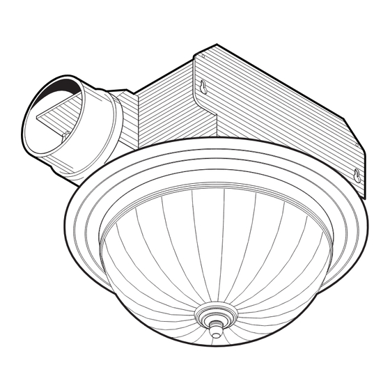
DECORATIVE VENTILATION
FAN WITH LIGHT
READ AND SAVE THESE INSTRUCTIONS
WARNING
TO REDUCE THE RISK OF FIRE, ELECTRIC SHOCK, OR
INJURY TO PERSONS, OBSERVE THE FOLLOWING:
1. Use this unit only in the manner intended by the manufac-
turer. If you have questions, contact the manufacturer at
the address or telephone number listed in the warranty.
2. Before servicing or cleaning unit, switch power off at
service panel and lock the service disconnecting means
to prevent power from being switched on accidentally.
When the service disconnecting means cannot be locked,
securely fasten a prominent warning device, such as a
tag, to the service panel.
3. Installation work and electrical wiring must be done by
a qualified person(s) in accordance with all applicable
codes and standards, including fire-rated construction
codes and standards.
4. Sufficient air is needed for proper combustion and
exhausting of gases through the flue (chimney) of fuel
burning equipment to prevent backdrafting. Follow the
heating equipment manufacturer's guideline and safety
standards such as those published by the National Fire
Protection Association (NFPA), and the American Society
for Heating, Refrigeration and Air Conditioning Engineers
(ASHRAE), and the local code authorities.
5. When cutting or drilling into wall or ceiling, do not dam-
age electrical wiring and other hidden utilities.
6. Ducted fans must always be vented to the outdoors.
7. DO NOT install in a tub or shower enclosure.
8. This unit must be grounded.
9. This unit is U.L. listed. Type I.C. inherently protected.
!
CAUTION
1. For general ventilating use only. Do not use to exhaust
hazardous or explosive materials and vapors.
2. This product is designed for installation in FLAT CEILINGS
ONLY. Do not mount this product in a wall.
3. The light fixture assembly must be mounted to the fan
housing assembly included with this product. Do not
mount the light fixture assembly to a wiring outlet box.
4. To avoid motor bearing damage and noisy and/or unbal-
anced impellers, keep drywall spray, construction dust,
etc. off power unit.
5. Please read specification label on product for further
information and requirements.
Installer:
Leave this manual with the
homeowner.
Homeowner:
Use and Care information on page 4.
TYPICAL INSTALLATIONS
POWER CABLE
MOUNTING TABS
CEILING
JOIST
HOUSING
HOUSING
CEILING
MATERIAL
LIGHT SHADE
HOUSING MOUNTED
DIRECTLY TO JOIST
2x6 (or larger)
Discharge parallel to joists.
ADDITIONAL
POWER CABLE
FRAMING
MOUNTING
TABS
HOUSING
I
"
"
JOIST
CEILING
MATERIAL
GRILLE
GLASS LIGHT SHADE
HOUSING MOUNTED TO "I" JOIST
Requires additional framing
for mounting tabs.
Discharge parallel to joists.
*
Additional framing must be a 2x6 (minimum height), at least 9-inches long.
PLAN THE INSTALLATION
INSULATION
(Place around and
over fan housing.)
FAN
HOUSING
POWER
CABLE*
Seal gaps
around
housing.
4-IN. ROUND
DUCT*
Seal duct
joints with
*Purchase
tape.
separately.
MODEL 745BNNT
POWER CABLE
2 x 4
CEILING
JOIST or
TRUSS
GRILLE
CEILING
PAN
MATERIAL
GLASS
HOUSING MOUNTED
TO 2x4 TRUSS
Requires additional framing
for mounting tabs.
Discharge parallel to joists.
*
4" ROUND
DUCT
I
"
"
JOIST
SUSPENDED
PAN
CEILING
MATERIAL
SUSPENDED CEILINGS
Housing hung with wires -
3-point mount.
OR
4-IN. ROUND
ELBOWS*
Page 1
ADDITIONAL
*
MOUNTING
FRAMING
TABS
2 x 4
CEILING
JOIST or
TRUSS
HOUSING
GRILLE
PAN
GLASS
LIGHT SHADE
POWER
CABLE
MOUNTING
HOUSING
TAB
GRILLE
PAN
GLASS
LIGHT SHADE
ROOF CAP*
(with built-in
damper)
Keep duct
runs short.
WALL CAP*
(with built-in
damper)
Advertisement
Table of Contents

Related Manuals for NuTone 745BNNT


Summary of Contents for NuTone 745BNNT
-
Page 1: Typical Installations
MODEL 745BNNT Page 1 DECORATIVE VENTILATION FAN WITH LIGHT READ AND SAVE THESE INSTRUCTIONS TYPICAL INSTALLATIONS WARNING TO REDUCE THE RISK OF FIRE, ELECTRIC SHOCK, OR POWER CABLE POWER CABLE ADDITIONAL INJURY TO PERSONS, OBSERVE THE FOLLOWING: MOUNTING FRAMING MOUNTING TABS TABS 1. Use this unit only in the manner intended by the manufac-... -
Page 2: Existing Construction
MODEL 745BNNT Page 2 INSTALL THE HOUSING - PLEASE NOTE - Existing Construction THE FOLLOWING INSTALLATION ILLUSTRATIONS SHOW 2 X 6 JOISTS. IF YOU HAVE A TRUSS OR “I”-JOIST INSTALLATION, MOUNT THE VENTILATOR TO THE ADDITIONAL FRAMING IN 1. Choose the location for your fan/light in the ceiling. For best THE SAME MANNER. -
Page 3: Install The Ductwork
MODEL 745BNNT Page 3 INSTALL THE DUCTWORK ATTACH THE GRILLE PAN AND GLASS SHADE FLUSH GRILLE PAN GRILLE SCREW LOCK WASHER COLLAR NOTE: The duct connector has a counter-balanced damper flap. The flap will be “open” approx. 1” when duct connector is attached to housing. -
Page 4: Service Parts
MODEL 745BNNT Page 4 USE AND CARE USE AND CARE CLEANING WARNING: DISCONNECT ELECTRICAL POWER SUPPLY AND LOCK OUT SERVICE PANEL BEFORE CLEANING OR SERVICING TO CLEAN GLASS SHADE AND GRILLE PAN: THIS UNIT. Remove glass shade. Shade can be wiped clean with a mild deter- gent solution or glass cleaner and dried with a soft cloth. -
Page 5: Instalaciones Típicas
MODELO 745BNNT Página 5 VENTILADOR DECORATIVA CON LA LUZ LEA Y CONSERVE ESTAS INSTRUCCIONES ADVERTENCIA INSTALACIONES TÍPICAS PARA REDUCIR EL RIESGO DE INCENDIO, DESCARGA ELÉC- TRICA O LESIONES PERSONALES, OBSERVE LO SIGUIENTE: 1. Utilice esta unidad solamente de acuerdo con las instrucciones del fabricante. Si tiene preguntas comuníquese con el fabricante a la dirección o al número telefónico que se indica en la garantía. 2. Antes de dar servicio o limpiar la unidad, interrumpa el suministro de energía en el panel de servicio y bloquee los dispositivos de desconexión para evitar la reinstalación accidental de la energía. -
Page 6: Instalación De La Cubierta
MODELO 745BNNT Página 6 INSTALACIÓN DE LA CUBIERTA - POR FAVOR NOTE - Construcción existente LAS SIGUIENTES ILUSTRACIONES DE LA INSTALACIÓN MUESTRAN VIGUETAS DE 2 X 6. SI LA INSTALACIÓN ES EN UNA VIGA O EN 1. Seleccione la ubicación del ventilador con lámpara en el cielo UNA VIGUETA EN “I”... -
Page 7: Conexión Eléctrica
MODELO 745BNNT Página 7 INSTALACIÓN DEL SISTEMA ACOPLE EL PLATILLO DE LA REJILLA Y LA PANTALLA DE CONDUCTOS DE VIDRIO AL RAS PLATILLO DE LA REJILLA TORNILLO DE LA REJILLA NOTA: El conector del conducto tiene una aleta compensadora ARANDELA COLLARÍN... -
Page 8: Uso Y Cuidado
MODELO 745BNNT Página 8 USO Y CUIDADO LIMPIEZA PARA LIMPIAR EL LENTE Y LA REJILLA: ADVERTENCIA: DESCONECTE LA CORRIENTE ELECTRICA Y Saque la tuerca de remate y sombrerete y quite la platalla. La BLOQUEE EL TABLERO DE SERVICIO ANTES DE LIMPIAR OR cortinilla puede limpiarse con una ligera solución detergente o...
Need help?
Do you have a question about the 745BNNT and is the answer not in the manual?
Questions and answers