Table of Contents
Advertisement
Quick Links
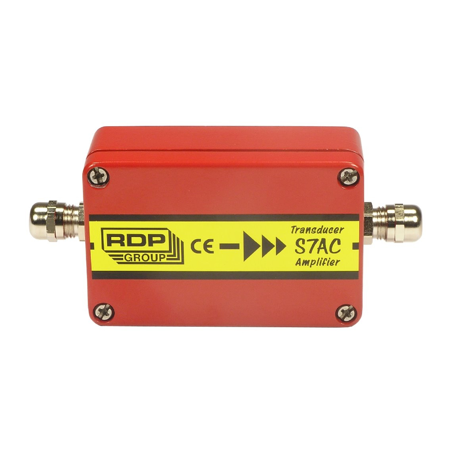
TRANSDUCER AMPLIFIER
This manual applies to units of mod status 10 ONWARDS
BS EN ISO 9001
Certificate No. FM13141
USA & Canada
RDP Electrosense Inc.
2216 Pottstown Pike
Pottstown, PA 19465
U.S.A.
Tel (610) 469-0850
Fax (610) 469-0852
E-mail
info@rdpe.com
www.rdpe.com
Technical Manual
TYPE S7AC
Doc. Ref CD1244G
RDP C
USTOMER
Affirmed by Declaration
of Conformity
All other countries
RDP Electronics Ltd
Grove Street, Heath Town,
Wolverhampton, WV10 0PY
United Kingdom
Tel: +44 (0) 1902 457512
Fax: +44 (0) 1902 452000
E-mail: sales@rdpe.com
www.rdpe.com
D
OCUMENT
Advertisement
Table of Contents

Subscribe to Our Youtube Channel
Summary of Contents for RDP Group S7AC
- Page 1 RDP C USTOMER OCUMENT Technical Manual TRANSDUCER AMPLIFIER TYPE S7AC Doc. Ref CD1244G This manual applies to units of mod status 10 ONWARDS BS EN ISO 9001 Affirmed by Declaration Certificate No. FM13141 of Conformity USA & Canada All other countries RDP Electrosense Inc.
-
Page 2: Table Of Contents
I N D E X INTRODUCTION ....................3 Certificate of EMC conformity ............... 4 INSTALLATION INSTRUCTIONS ..............5 EMC Requirements ..................5 Connections General ..................6 Typical supply/output connections ..............7 Transducer connections (LVDT and half bridge) .......... 8 CONTROLS ..................... 10 Voltage/Current Output ................ -
Page 3: Introduction
INTRODUCTION The S7AC is a signal-conditioning unit for use with transducers requiring AC excitation and synchronous demodulation, producing a DC output voltage or current. Units may be master-slaved in systems where carrier frequency beating is a problem. The unit is housed in a robust aluminium case with connections via glands, all sealed to IP65 specification. -
Page 4: Certificate Of Emc Conformity
Certificate of EMC conformity DECLARATION OF CONFORMITY RDP ELECTRONICS LTD. Grove Street, Heath Town Wolverhampton, West Midlands WV10 0PY United Kingdom We declare that the product described in this technical manual is manufactured by RDP Electronics Limited and performs in conformity to the following: The Electromagnetic Compatibility Directive 2014/30/EU RoHS2 Directive 2011/65/EU R D Garbett... -
Page 5: Installation Instructions
NOTES: Cable shields to be grounded at only one end - the S7AC end, although earthing at both ends may reduce the effects of high frequency EMI. When the S7AC is a small part of a large electrical installation, ensure the cables to and from the S7AC are segregated from electrically noisy cables. -
Page 6: Connections General
Connections General Transducer and supply/output connections are made via two screw-clamped terminal blocks mounted on the circuit board adjacent to the two cable glands as shown in Fig.1. To reverse output polarity, reverse Signal Hi/Signal Lo. With all supplies, voltage output is between OUTPUT and COMMON, which is internally connected to Excitation Lo. -
Page 7: Typical Supply/Output Connections
Typical supply/output connections Voltage output, single supply (ensure SP1 is NOT linked, see fig. 1) This arrangement should only be used if (c) is not possible. If this arrangement is used, either the supply V- or the output common (or both) must be fully floating. -
Page 8: Transducer Connections (Lvdt And Half Bridge)
See fig. 1 (or amplifier PCB) for pin designations. Most RDP LVDT transducers also have a BLACK wire. This is not required with the S7AC amplifier and should be insulated and left unconnected. If the above configuration does not give the required output phase (i.e. the output rises for outward transducer movement instead of falling);... -
Page 9: Fig. 3 Signal Cable Installation For Optimum Emc
Fig. 3 Signal Cable Installation for Optimum EMC Cable Cores Trim Rubber Seal Cable Shield Double Back Plastic Sleeve Cable Over Plastic Sleeve Insert the end of the cable, plus the plastic sleeve into the metal outer shell of the gland. -
Page 10: Controls
(0.230/5) x 1 x 50=2.3V The standard excitation of the S7AC is 1V, as used in the calculations above. The following table shows the band of transducer full-scale output voltages appropriate to each of the 8 Gain Range Settings. For example, a transducer with a full-scale output of 2.3V would be correctly set as gain range 3. -
Page 11: Coarse Zero
Coarse Zero A 5-way toggle switch, SW2, (toggle 6 – see section 3.5) provides output zero shifts of about 1V per step (with Fine Gain at minimum – up to 4V at maximum). When used with FINE ZERO will suppress any output (up to 5V) to zero. All toggles OFF is normal, ie no suppression applied. -
Page 12: Setting Up Procedures
SETTING UP PROCEDURES LVDT & Half Bridge (Differential Inductance) Transducers 4.1.1 Determine the transducer output from the manufacturer's data sheet and set the Coarse Gain control as shown in Sections 3 and 4. 4.1.2 Connect the transducer to the 5-way connector as detailed in Section 2. Switch ON power and allow a 15-minute warm-up period (for maximum accuracy). -
Page 13: Fig. 4 Maximum Output Voltage Vs. Supply Voltage
Fig. 4 Maximum Output Voltage vs. Supply Voltage 10 2 4 6 8 10 12 14 16 18 20 22 24 26 28 30 Total Supply (V+ to V-) Voltage in Volts Fig. 5 Maximum load resistance for 20mA output vs. Supply Voltage 2 4 6 8 10 12 14 16 18 20 22 24 26 28 30 Total Supply (V+ to V-) Voltage in Volts... -
Page 14: Specification
SPECIFICATION Supply ±6 to ±18V dc or 12 to +36V dc at 50mA typical Voltage Output – dual supply ±4±10V into 2k } Refer to single supply ±4V to ±10V into 10k } Fig.4 Regulation 0.5mV/V typical Current Output- both supplies 4-20mA into 100/550... - Page 15 Notes...
-
Page 16: Warranty And Service
WARRANTY AND SERVICE WARRANTY. R.D.P. Electronics products are warranted against defects in materials or workmanship. This warranty applies for one year from the date of delivery. We will repair or replace products that prove to be defective during the warranty period provided they are returned to R.D.P.


Need help?
Do you have a question about the S7AC and is the answer not in the manual?
Questions and answers