Table of Contents
Advertisement
Quick Links
Advertisement
Table of Contents

Summary of Contents for 10-8 Video HD4SD
- Page 1 10-8 HD4SD 4-Ch Dual SD HD MDVR Installation / User Manual 2016r1...
- Page 2 All Products • Three (3) year free replacement of any failed component. Car Camera Components 1. Call 1-888-788-1048 and ask for Technical Support. 2. Visit 10-8video.com and click on the Support Section to request a RMA. Shipping Address 10-8 Video LLC 1423 Huntsville, Hwy. Suite F Copyright © 2011-2016 10-8 Video Digital Evidence Solutions. • All rights reserved. Fayetteville, TN 37334 Disclaimer: 10-8 Video Digital Evidence Solutions reserves the right to make changes in specifications at any time and without notice. The information provided by this document is believed to be accurate and reliable. However, no responsibility is assumed by 10-8 Video Phone Numbers Digital Evidence Solutions for its use; nor any infringements of patents or other rights of (888) 788-1048 • (931) 233-8550 third parties resulting from its use. No license is granted under any patents or patent rights of 10-8 Video Digital Evidence Solutions.
-
Page 3: Table Of Contents
GPS Related Problems Step 3: Set Vehicle Info CMS Related Problems Step 4: User Setup Reference Tables Step 5: Display Setup 10-8 HD4SD Memory Space Reference Tools Required for 10-8 HD4SD Installation Software Recording Setup 10-8 HD4SD Additional Parts Needed Step 1: Enter the Recording Setup Interface Revision History Step 2: Record Basic Setup Interface Step 3: Channel Mode... -
Page 4: Safety
4. Do NOT spray any liquid on the device to prevent an internal short circuit or fire. 10-8 Video, or its branches are not liable in full or in part for 5. Do NOT place any other device directly on top of the camera(s). improper installation resulting in loss or damage to your property, or for voiding all or part of the vehicle manufacturer’s warranty. -
Page 5: Product Overview
Product Overview Specifications Product Description Technical Specifications The 10-8 HD4SD is a dual SD card HD MDVR especially designed for use in vehicles. If features four (4) channels of D1/960H/720P video and audio Item Parameter Description recording and playback, four (4) channels of AHD 720P and one channel Language English of IPC HD video via a full frame recording camera. It also utilizes one of Operating the most advanced H.264 video encoding/decoding codecs in the industry Graphical user interface System Interface today. Password User password and Admin password management & Security The mobile MDVR is powered by an ARM DSP fast dual-core processor • 4-channel analog video input running on an embedded Linux OS. It also features 3G/4G network •... -
Page 6: Electrical Specifications
Specifications Technical Specifications (Continued) Electrical Specifications Item Parameter Description Item Parameter Description Alarm Input Eight (8) alarm inputs. You can set the lower level alarm 8V~36V, Check that the power supply is working within this (1V or below) or upper level alarm (5V or above) Power Supply +8~+36V range before use;... -
Page 7: System Schematic
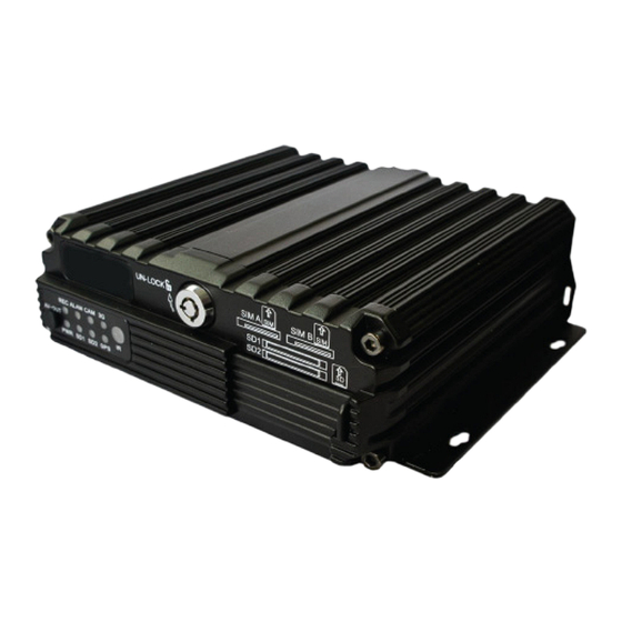
System Schematic Introduction to Mainframe FIG. 2 DVR Mainframe Schematic FIG. 1 DVR Mainframe NOTE: Actual camera appearance may vary from illustration. -
Page 8: Hardware: Installation
Hardware: Installation DVR Remote Control Device and Installation 1. Installation 2 Camera Menu Split Screen Step 1: Open the protective cover. Cancel Turn the electric lock located on the front panel counter- clockwise to unlock it and open the protective cover. Left SD Card Info Right Play Down Pause Return to Previous Stop Menu Information Fast Forward Enter/Select Rewind FIG. - Page 9 Hardware: Installation Step 2: Install SIM and SD card (FIG. 4) Step 3: Lock the electronic lock. (FIG. 4) As indicated on the panel, install SD card with its face up into After all the SD cards and SIM cards are installed, pull the its slot. Two SD cards are supported (maximum 128GB for each). protective cover to the right side and close it. Then turn the Then insert the SIM card (if equipped) with its face up and the electronic lock counter-clockwise to lock it. The device can now “cut” forward into the SIM slot and press it into place. Note the be powered on. front and back face when inserting the SIM card. Depending upon the device’s communication configuration, The device will not power on unless the protective cover is install the related SIM card for either the 3G or 4G capabilities if closed and the electronic lock is in the locked position.
- Page 10 Hardware: Installation Step 4: Installing the MDVR Step 5: Install the GPS, 3G/4G and/or WiFi Antenna (if equipped) The MDVR can be installed in any direction; there is no need for any part of the device to be pointed in a specific direction. Depending upon your device’s options, connect the corresponding GPS, 3G/4G and or WiFi antenna(s) to their Install the MDVR into a convenient location inside your vehicle corresponding interface(s) (see FIG. 2) on the rear panel of the noting the mounting hole positions in the diagram below MDVR. Keep your wires organized and arranged properly to (FIG. 6). maintain the most optimal signal conditions and to protect the signal from external interference. Even though the device can be mounted in any direction, mounting the device horizontally will ensure it will work even under extreme conditions. A horizontal mounting will help protect it against water, humidity and condensation collecting in the housing and causing a motherboard short circuit. FIG. 6 Mainframe Dimensions and Mounting Hole Positions WiFi Hardware Installation...
- Page 11 Hardware: Installation Step 6: Connect the power cord. Connect the 6-pin white plug to the 6-pin power input port on the rear panel of the MDVR. The red and black cables are Yellow directly connected to the battery of the vehicle, i.e. positive Negative terminal and negative terminal respectively, or to the main power. Positive 12V 55AH The yellow cable is connected to ACC, the vehicle control DC12-5A circuit switch (used to start the vehicle’s motor). The unit will automatically power on when the car key is in the ON position and power off when the key is in the OFF position. When the device is not installed in a vehicle (such as monitoring Check that the battery provides voltage between 8V~36V systems in a bus station, logistics transfer) or under testing before connection to prevent damage to the device. conditions, you can use a switching power above DC12V-5A to supply the MDVR the proper signal. In this case, twist the red 2.
- Page 12 Hardware: Installation Step 7: Connect the A/V Output Cable SWITCH +12V This product features two video outputs (one is a φ3.5 phone jack on the front panel and the other is a 24PIN connector in the rear). MDVR SENSOR Use the rear A/V cable for most mobile installations. FIG. 9 High Level Alarm Block Diagram Step 8: Connect the alarm input and output cables. Note that the input alarm wires are labeled as to where they will be used in a typical installation: Blue ‘Mic Trigger’: Connect to blue wire from wireless mic cradle Orange ‘Lights’: Connect to 12v wire that will be ‘Hot’...
-
Page 13: Dvr: Setup
DVR: Setup Software Settings Overview Software General Setup After the power supply is connected to the vehicle’s start circuit, ensure Step 1: Basic Setup the device will automatically start when the vehicle is started. This verifies the power supply is properly connected to the peripherals. From the Setup menu, select the General option and press the “ENTER” button to enter the General interface, where you After the vehicle starts, the system will enter the Quad View. Here you can can set your desired date and time, vehicle information, user press the Login button on the remote control to input the Admin password management, network and display. (888888 by default) to enter the setup menu and configure related settings. The setup has seven (7) options including: General, Record, Alarm, Tools, Peripherals, Search and System Info (as shown in FIG 10). The following section will individually introduce individual settings. The 10-8 System will come pre-configured and suitable as-is for most departments. The only settings that will need to be set is the date/time for your area and the Vehicle Info screen. -
Page 14: Step 2: Set Date & Time
DVR: Setup (General) Step 2: Set Date & Time Step 3: Set Vehicle Info From the General menu, select “Date & Time” to enter its Press the “Return” button to return to the General menu to the interface. enter the Vehicle Info menu. To facilitate unified management of vehicles on the server, it is recommended to completely fill in vehicle information. If GPS timing mode is selected, the time will be updated at the “Timing Time”. The server will monitor and manage vehicles through You can select device number. timing mode/ When vehicles ignition mode. By are managed via default, ignition a 3G/4G network, mode is used, where please ensure the you can set the uniqueness of the... -
Page 15: Step 4: User Setup
DVR: Setup (General) Step 4: User Setup Step 5: Display Setup Press the “RETURN” button to return to the General menu to Press the “RETURN” button to return to the General menu to enter the User Setup menu and to enable the password feature. enter the Display Setup interface. The original admin password is 888888. If the password is changed the password will be required when re-entering the system setup menu. Select PAL/NTSC according to the proper format in your region. Use NTSC in the US. FIG. 15 Display Setup Menu FIG. 14 Security Setup Menu When viewing videos on the screen you can choose whether to have the date &... -
Page 16: Software Recording Setup
DVR: Setup (Recording) Software Recording Setup Step 2: Record Basic Setup Interface From the Record Setup Menu, select the General options and press the “ENTER” button to enter the Record Basic Setup Step 1: Enter the Recording Setup Interface interface. Here you can select the desired recording method. Press the “RETURN” button twice to return to the Setup Menu, where you can configure recording settings, including general settings, main code, sub-stream, recording schedule, mirror recording, SD recording and alarm recording. When this option is enabled, the oldest videos will be overwritten as needed when SD space is limited. This si the recommended setting so that no events are missed. -
Page 17: Step 3: Channel Mode
Table 1 higher the picture quality Camera Connection Modes is, the netter the video definition will be. FIG. 18 Connection Connection Model 10-8 HD4SD Channel Mode Interface Mode Diagram Connection of a single 4 ways of D1/960H/720P AHD video inputs analog camera available. To ensure your option changes are saved when you are done, move your cursor to the “Save”... -
Page 18: Step 4: Sub-Stream Setup (Wifi Option Only)
DVR: Setup (Recording) Step 4: Sub-Stream Setup (WiFi Option Only) Step 5: Recording Schedule (to be set in timing record mode NOT recommended for Department use) Press the “RETURN” button to return to the Record Setup Menu, then enter the Sub-Stream settings interface. Press the “RETURN” button to return to the Record Setup Menu, then enter the Recording Schedule settings interface. This setting is directly related to definition and fluidity of the video on the CMS software. The higher the resolution, If “Timing Record” mode (not commonly used) is selected frame rate and bit rate are, the better looking the video will under Record Mode in the General Options, you must set the be. However, this requires more storage space, memory and record time frame here (two time frames can be selected). -
Page 19: Alarm Setup
DVR: Setup (Alarm) Alarm Setup Step 2: Sensor Setup This device provides eight (8) SENSOR-IN inputs and can be set with a high level alarm. From the Alarm Setup menu, select Step 1: Enter the Alarm Setup interface. the “Sensor” icon, and press the “ENTER” button to enter the Press the “RETURN” button to return to the Setup Menu, and sensor alarm options. Set the alarm “Enable” to “ON” and select the Alarm Setup interface. Here you can set the sensor, name the sensor as required. speed, acceleration, temperature, motion detection, linkage settings and other alarm modes. The alarm feature can only be used when an external sensor is connected. You can select the video monitoring channel Different types of recordings are created depending which corresponding to this alarm type you choose for each alarm setting. sensor. When the alarm is triggered, the monitor • If an “Event” is selected for the alarm type, a normal will automatically pop up this channel and recording is conducted. -
Page 20: Step 3: Speed Setup
DVR: Setup (Alarm) Step 3: Speed Setup Step 4: G-Sensor Setup Press the “RETURN” button to return to the Alarm Setup menu, Press the “RETURN” button to return to the Alarm Setup menu, and then select the Speed Setup interface. If the temperature and then select the G-Sensor Setup interface. When transient alarm feature is enabled, this information can be transmitted to acceleration is high during braking, turning, acceleration or the central CMS system. collision, the sensors will indicate that the threshold value has changed quickly. The G-sensor alarm requires calibration when This setting will trigger a initially set. Stop the vehicle recording when the vehicle on a flat, level surface to reaches the set speed. Low set it. speed is not used in normal use. FIG. 23 FIG. 24 Speed Setup Interface G-Sensor Setup Interface To ensure your option changes are saved when you are done,... -
Page 21: Step 5: Temperature Setup (Not Currently Used)
DVR: Setup (Alarm) Step 5: Temperature Setup (NOT currently used) Step 6: Motion Detection Setup (NOT currently used) Environmental changes may be detected more easily when the sensitivity is set high; however, change of brightness and color will also trigger an alarm. FIG. 26 Motion Detection Setup Interface You can use your remote control within the detection area to select two points as a diagonal to define a detection area. Within the user defined area, when there is an object moving, the system will give an alarm when it is detected. A user can search motion detection alarm events under FIG. 25 “Configuration Log Search”, naming “CHL MD alarm”. Temperature Setup Interface How to Set a Detection Area: 1. Select “Setup”, and press the “Enter” button on the remote to enter... -
Page 22: Step 7: Linkage Setup
DVR: Setup (Alarm) Step 7: Linkage Setup Press the “RETURN” button to return to the Alarm Setup menu, and then select the Linkage Setup interface. This device provides two alarm outputs. You can select none/output 1/output 2 from the linkage setup menu. 12V of high level is generated to drive other optoelectronic devices when the related alarm is triggered. (For detailed connection methods, please refer to the alarm input/output cable connection section. Open to record related This page left intentionally blank. alarm logs. FIG. 27 Linkage Setup Interface Enabling or disabling of write metadata is used to check if related alarm information is written tot the video file. -
Page 23: Software: Configuration
Software: Configuration Configuration Step 1: Configuration Management Step 2: Formatting SD Cards Press the “RETURN” button to return to the Setup Menu, and Press the “RETURN” button to return to the Setup Menu, and then select the Tools icon. Then select the Configuration icon to then select the Tools icon. Then select the Format icon to enter enter the Configuration interface. Here you can import/export the Format interface. Here you can select the storage medium to configuration settings through an SD card or reset to the MDVR be formatted and press the “Format” button. to its factory settings. FIG. 28 Accessing the Configuration Interface FIG. 29 Formatting Media Interface Software: Configuration... -
Page 24: Step 3: Log Search
Software: Configuration Step 3: Log Search Search and Replay Recordings Press the “RETURN” button to return to the Setup Menu, and Press the “RETURN” button to return to the Setup Menu, and then select then select the Tools icon. Then select the Log icon to enter the the Search icon to enter the Record Search interface. You can play the video Log Search interface. files that appear in the search results. The calendar days with a green background indicate that there is a log that can be searched by selecting the date, time, record type and related channel. The calendar days with green backgrounds indicate that there is a log that can be searched for by selecting date, time and log type. FIG. 30 Log Search Interface FIG. 31 Recordings Playback Workflow... -
Page 25: Software: System Information
Software: System Information Software: System Information System Information In Quad view mode, you can either press the “INFO” button on your remote control or enter the setup menu to display the system information using the System Info icon. This page left intentionally blank. FIG. 32 System Information Workflow... -
Page 26: Appendix
3. Check the connection status of the video output cable and display. GPS Related Problems GPS module is present but no coordinate information is available. 4. Check the lock status on the 10-8 HD4SD lock; the device can only be started when the lock is locked. 1. Check if the GPS module is indeed present; also check if the HDD is installed and properly contacted. The 10-8 HD4SD video interface is different from the camera input 2. Check if the GPS antenna is properly contacted and if the antenna interface. is broken. The antenna is recommended to be placed in an area having a strong signal. Note that some car glass shielding may A 4-pin interface is used for the vehicle device. BNC interface or air interfere with receiving a proper GPS signal. interface is used for the camera. If inconsistency is found, please use an adapter or connect it to a standard line defined as the line sequence for 3. If the test is conducted indoors and the GPS antenna is also... -
Page 27: Cms Related Problems
Appendix CMS Related Problems The device reports information to the CMS, but after a period of time it ceases to transmit video. 1. Check if the device information displays dial-up. If it does then the The device is powered on while the CMS client does not display traffic for the SIM card may be used up. Replace it with a new SIM vehicle information or video. card. -
Page 28: Reference Tables
Appendix Reference Tables 10-8 HD4SD Memory Space Reference Picture Quality Tools Required for 10-8 HD4SD Installation Name Specification Description Resolution Multimeter As Needed Test the electrical circuit Drill Bit As Needed Create holes for mounting Video Remote Record Special Tool... -
Page 29: 10-8 Hd4Sd Additional Parts Needed
Appendix Revision History ___________________ for: (Enter Serial Number Here) 10-8 HD4SD Additional Parts Needed (Not Included) Item Item Tie Straps Power cord Electrical Tape Self Tapping Screws Fire Resistant Cable Housing ACC Cable Wire Clips Appendix...
Need help?
Do you have a question about the HD4SD and is the answer not in the manual?
Questions and answers