Table of Contents
Advertisement
Quick Links
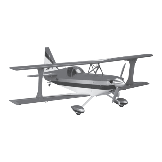
The Ultimate ARF
Wingspan: 60.5 in [1535mm]
2
Wing Area: 1250 in
[80.6dm
Weight: 11.75 – 12 lb [5330 – 5445g]
Wing Loading: 22 oz/ft
2
[67g/dm
Length: 66 in [1675mm]
Radio:
5-channel minimum
Servos: (6) Futaba 9001 servos, (1) Futaba 9202 servo (rudder),
(1) Futaba 3003 servo (throttle)
Engine
.90 – 1.20 cu in [15 – 20cc] two-stroke,
1.20 – 1.50 cu in [20 – 25cc] four-stroke
Carl Goldberg Products Ltd. has inspected and certifi ed the
components of this aircraft. The company urges the buyer to
perform their own inspection, prior to assembly, and to immediately
request a replacement of any parts they believe to be defective
for their intended use. The company warrants replacement of any
such components, provided the buyer requests such replacement
within a period of 90 days from the date of purchase and provided
the defective part is returned, if so requested by the company.
No other warranty, expressed or implied, is made by the company
with respect to this kit. The buyer acknowledges and understands
that it is their responsibility to carefully assemble the fi nished fl ying
model airplane and to fl y it safely. The buyer hereby assumes full
responsibility for the risk and all liability for personal or property
damage or injury arising out of the buyer's use of the components
of this kit.
READ THROUGH THIS MANUAL BEFORE STARTING CONSTRUCTION. IT CONTAINS IMPORTANT
INSTRUCTIONS AND WARNINGS CONCERNING THE ASSEMBLY AND USE OF THIS MODEL.
Entire Contents © Copyright 2008
2
]
2
]
INSTRUCTIONS
Welcome to the world of Ultimate fl ying! Now that you're an
experienced R/C pilot, you're ready to step up to a higher level
of aerobatic fl ying. And we've made sure this ARF version won't
disappoint. With the same fl ight characteristics as the kit version,
you'll soon know why the Carl Goldberg Products Ultimate
has been America's favorite sport biplane since 1990.
LIMITED WARRANTY
If the buyer is not prepared to accept the liability associated
with the use of this product, the buyer is advised to return
this kit immediately in new and unused condition to the place
of purchase.
To make a warranty claim send the defective part or item to Hobby
Services at the address below:
Include a letter stating your name, return shipping address, as
much contact information as possible (daytime telephone number,
fax number, e-mail address), a detailed description of the problem
and a photocopy of the purchase receipt. Upon receipt of the
package, the problem will be evaluated as quickly as possible.
™
Hobby Services
3002 N. Apollo Dr., Suite 1
Champaign, IL 61822 USA
Champaign, Illinois
(217) 398-8970
www.carlgoldbergproducts.com
GBGZ1047 for GBGA1047 V1.0
Advertisement
Table of Contents

Summary of Contents for Carl Goldberg Models The Ultimate ARF
- Page 1 The Ultimate ARF Wingspan: 60.5 in [1535mm] Wing Area: 1250 in [80.6dm Weight: 11.75 – 12 lb [5330 – 5445g] INSTRUCTIONS Wing Loading: 22 oz/ft [67g/dm Welcome to the world of Ultimate fl ying! Now that you’re an Length: 66 in [1675mm] experienced R/C pilot, you’re ready to step up to a higher level...
-
Page 2: Table Of Contents
You will also need: ❏ (4) 8-32 x 1-1/4" [32mm] SHCS bolts (GPMQ3050) ❏ Fuel plug “dots” (GPMQ4166) TABLE OF CONTENTS ❏ Standard fuel clunk (DUBQ0637) ❏ A suitable Pitts-style muffl er REQUIRED ITEMS ............2 Engine ................ 2 If you’re going to use a three line fuel tank you’ll also need a Radio Equipment ............ -
Page 3: Prepare For Assembly
PREPARE FOR ASSEMBLY ❏ 2. Prepare sixteen (16) CA hinges by placing a T-pin through the center of each hinge. Slide the hinges into the hinge slots of each wing. ❏ 3. Fit the ailerons to each wing. Note: All ailerons are identical with respect to shape and hinge slot location, but you must be careful to mount left side ailerons to the left Before you begin assembling your airplane, take the time now... -
Page 4: Servo & Control Horn Installation
❏ ❏ 6. Hold the aileron in its full defl ected position as you’re pushing in and apply 10 to 12 drops of thin CA to each hinge. Turn the wing over and apply CA to the opposite side of the hinges. ❏... - Page 5 ❏ ❏ 12. Locate the four (4) 3-1/4" [83mm] long aileron pushrods and four (4) plastic clevises. Thread the clevises onto the pushrods so that 1/16" [1.6mm] of thread is exposed on the inside of the threaded barrel of the clevis. Slide a silicone clevis retainer onto the pushrod.
-
Page 6: Wing Dowel Installation
WING DOWEL INSTALLATION ❏ 1. Locate the two 5/16" x 2" [8 x 51mm] wing dowels. Test fi t each dowel in the LE of the pre-drilled holes of the lower wing. To help installation in the fuselage later, you may round the tip of each dowel using sandpaper. -
Page 7: Flying Wires Installation
is perpendicular to the stab. You can hold it in position with masking tape. ❏ 12. As you’re waiting for the epoxy to cure, you can jump ahead and build up your landing gear. ❏ 7. Coat the top and bottom of the stab with 30-minute epoxy. - Page 8 necessarily want these to be equal lengths on both sides – just make sure that the stab and fi n are both aligned. ❏ 4. Measure 4-1/8" [105mm] forward from the TE of the fuselage (the rudder hinge line) and draw a line straight ❏...
-
Page 9: Hinge The Tail Control Surfaces
HINGE THE TAIL CONTROL SURFACES ❏ 1. Prepare six (6) hinges and slide them into the horizontal stabilizer. ❏ 2. Being mindful of the trim scheme, fi t the left elevator to the left stab and the right elevator to the right stab. ❏... - Page 10 ❏ ❏ 6. Center your servos and install a long servo arm onto 3. Use the servo lead strings that you used previously for the aileron installation to help you route your elevator servo leads. each elevator servo. Choose the arm that points up and is 90 Tie a spare nut or a servo wheel to the end of the string.
-
Page 11: Rudder Servo & Control Installation
❏ 10. Attach each pushrod to the outermost hole of the elevator control horns. ❏ ❏ 11. Tape or hold the elevator in the neutral position. Extend the pushrod to the third hole out from the center of the servo arm. Make a 90° bend at the mark. ❏... - Page 12 former directly ahead of the cable exit holes. Be sure to route the cable through the hole in the former. ❏ 11. Visually inspect the cable routing. Make sure that your rudder cables will not interfere or become tangled in the elevator servo leads.
-
Page 13: Engine Installation
ENGINE INSTALLATION FIT THE ENGINE ❏ 5. Drill four 7/32" [5.6mm] holes for the engine mount bolts. Drill a 5/32" [4mm] hole for the throttle pushrod while you’re at it. If you’re going to use a three line fuel tank setup, go ahead and drill a third hole now. -
Page 14: Trim The Cowl
TRIM THE COWL ❏ 5. Trace around the openings in the templates you made. Use a Dremel tool to cut a hole in the cowl for the cylinder ❏ head, muffl er, and needle valves. Fit the engine and muffl er 1. -
Page 15: Radio Installation
RADIO INSTALLATION ❏ 4. Install the throttle servo. ❏ 1. Install a new radio switch in the right side of the fuselage. There is a cutout for a switch there. Optionally you can install a switch and charge jack, but you will need to mount it up higher along the same former. -
Page 16: Fuel Tank & Battery Installation
❏ ❏ 3. Connect your servo leads and the battery switch lead to 2. Assemble the stopper as shown with the vent line the receiver. Connect a Y-harness to your aileron channel. Wrap pointing up to the top of the tank. The top of the tank must be the receiver in latex foam rubber and install it in the fuselage. - Page 17 ❏ ❏ 2. Use one large tie wrap to attach your battery to the fuel 6. Use the 6" [152mm] stick to support the fuel tank. Push tank tray. Note: You may need to drill a few holes in the tray the tank tray forward until it is locked into the fi...
-
Page 18: Landing Gear Installation
LANDING GEAR INSTALLATION MAIN LANDING GEAR INSTALLATION ❏ 4. Remove the wheel collars and fi le fl at spots on the bottom side of each axle. ❏ 1. Collect the following parts: One (1) landing gear strap, two (2) wheel pants, two (2) 3-1/4" [83mm] axles, two (2) self-locking axle nuts, four (4) wheel collars, four (4) 4-40 x 1/2"... -
Page 19: Tail Wheel Installation & Rigging
TAIL WHEEL INSTALLATION & RIGGING ❏ 7. Install two 4-40 blind nuts in each wheel pant from the inside. ❏ 1. Collect the following parts: One (1) tail wheel landing gear strap, one (1) tail wheel wire, one (1) 1-1/4" [32mm] tail wheel, one (1) steering arm assembly, one (1) large area wheel collar, one (1) standard collar, two (2) springs, and two (2) 4-40 x 1/2"... -
Page 20: Final Assembly
❏ 4. Rotate the threaded joints until the center hole of the joint is approximately 1" [25mm] from the center of the tail ❏ 8. Install the tail wheel springs onto the tail wheel steering wheel wire. Make each side equal. Note: You may want to arms and connect them to the rudder control horns as adjust these later to get the tail wheel steering throw that shown. -
Page 21: Wing Installation
WING INSTALLATION layer of 30-minute epoxy to the bottom of the reinforcement plate and set it in place. Glue the reinforcement plate in place ❏ 1. Set your lower wing in position over the fuselage by lightly snugging down the wing bolts. As a precaution, and tuck the extensions into the fuselage. -
Page 22: Setting Control Throws & Direction
SETTING CONTROL THROWS & DIRECTION ❏ 9. Set the top wing in position and thread the interplane struts into the top wing fi nger-tight. ❏ 1. Turn your radio on and neutralize all of your trims. Check to see that your controls are operating in the correct direction by standing behind the model and moving the sticks. -
Page 23: C.g. Balancing
and adjust the tension of both cables evenly. Tension the cables until there is no slack in the cables when you apply light pressure to the rudder with the servo fi xed. Make sure that the rudder itself is still centered once you have the C.G. -
Page 24: Flight Log
FLIGHT LOG Date Built: Date of First Flight: Flight Notes:...
Need help?
Do you have a question about the The Ultimate ARF and is the answer not in the manual?
Questions and answers