Table of Contents
Advertisement
Advertisement
Table of Contents

Summary of Contents for NetBotz wallbotz 500
- Page 2 Preface Copyright © Copyright NetBotz Inc. 2000 - 2005 Trademarks BotzWare, NetBotz, RackBotz, WallBotz, and the NetBotz symbol are registered trademarks of NetBotz, Inc. Other brand and product names are registered trademarks or trademarks of their respective holders. Federal Communications Commission...
- Page 3 Jack - 4 Pin Power Din Leakage Current - Less than 3.5 VCCI Cleaning Use only a dry cloth to clean the NetBotz appliance. To clean your NetBotz appliance, gently wipe the surface of the NetBotz appliance with a dry cloth. Misuse Use your NetBotz appliance ONLY in the manner specified.
- Page 4 THE IMMEDIATE TERMINATION OF YOUR LICENSE RIGHTS THEREUNDER. Availability of Open Source Technologies The WallBotz 500 product includes technologies that are governed by the GNU Public License. The GPL source code contained in our products is available for free download from: http://support.netbotz.com/gpl...
- Page 5 Preface...
-
Page 6: Table Of Contents
Administrator Account User ID & Password..........6 Root Account User ID & Password.............. 7 The WallBotz 500: A Closer Look About the WallBotz 500 Base Station............9 WallBotz 500 Base Station LEDs ............11 About the Camera Pod 120................12 About the Camera Pod 120’s Imaging Modes........ - Page 7 Installing an Undocked Camera Pod 120..........46 Installing an Undocked Sensor Pod 120..........47 Installing Hardware Options Adding Pods to Your WallBotz 500............... 49 Installing and Configuring a CCTV Adapter Pod 120........ 51 Connecting an Output Relay Pod 120............53 Connecting a Power Control Pod.............
-
Page 8: About Your Wallbotz 500
And when used in conjunction with Output Relay Pod 120s and Power Control Pods your WallBotz 500 can automatically or interactively turn lights on or off, open door locks, cycle power, and so forth. -
Page 9: Upgrading Your Wallbotz 500
Your WallBotz 500 supports a variety of hardware and software upgrades. These upgrades, including add-on software applications, external sensors, and the ability to connect multiple Camera and Sensor Pod 120s to a single WallBotz 500 are About Your WallBotz 500... -
Page 10: Hardware Upgrades
(external sensors must be connected to a Sensor Pod 120), and Power Control Podss and supported RS232-based sensors (Power Control Pods and RS232-based sensors and devices must be connected to the WallBotz 500 using a USB-to- serial port adapter). Available external sensors include TS100 External... - Page 11 Add-on software is available for purchase separately from NetBotz and NetBotz certified resellers. About Your WallBotz 500...
-
Page 12: Before You Begin
Wall mounting bracket (high-quality, heavy-duty, 360° positionable wall-mounting bracket for use with either the WallBotz 500 base station or a tethered Camera Pod 120) Wall mounting bracket (small black metal bracket for use in mounting a tethered Sensor Pod 120) -
Page 13: Gathering Network Settings Information
If you use a default gateway, what is the IP address of the gateway? Administrator Account User ID & Password Your WallBotz 500 comes with a pre-configured Administrator account. The User ID and Password for this pre-configured account are: User ID: netbotz... -
Page 14: Root Account User Id & Password
Root Account User ID & Password Your WallBotz 500 comes with a pre-configured root account. The root account is used only for appliance communications that are performed using the serial port, such as when you use the Serial Configuration Utility to specify network settings (see “Using the Serial Configuration Utility”... - Page 15 Before You Begin...
-
Page 16: The Wallbotz 500: A Closer Look
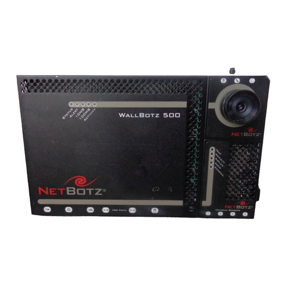
The WallBotz 500: A Closer Look Your WallBotz 500 consists of 3 separate components: the WallBotz 500 base station, the Camera Pod 120, and the Sensor Pod 120. Detailed information about each of these components follows. About the WallBotz 500 Base Station... - Page 17 PC Card Slot. For adding PC Card-based hardware upgrades, such as a supported wireless LAN adapter or PC Card modem, to your WallBotz 500 appliance. The PC Card slot supports 3.3V and 5V cards, and both 16 Bit PC Cards and 32 Bit Cardbus cards.
-
Page 18: Wallbotz 500 Base Station Leds
WallBotz 500 Base Station LEDs Your WallBotz 500 base station features a series of 5 LED indicators, shown below. These LEDs are used to indicate the current power, alert, and network communication status of the appliance. Description Status Indicates the current operational status of the appliance. -
Page 19: About The Camera Pod 120
One Camera Pod 120 comes docked to the WallBotz 500. This pod includes a USB header that enables the pod to be docked with the WallBotz 500 base station and a USB port that enables the pod to be tethered to the base station using a standard USB cable. - Page 20 Integrated Speaker Sensor: State sensor that reports whether a speaker plug is inserted into the Speaker jack on the pod. Activity LED, which indicates the power-on and recording status of the pod. The WallBotz 500: A Closer Look...
-
Page 21: About The Camera Pod 120'S Imaging Modes
1280x1024 are needed. 1280x1024 images still contain the entire field of view, but lower image resolution modes use only a portion of the frame, determined by a user-specified 640x480 window of interest. The WallBotz 500: A Closer Look... - Page 22 Scan mode shows a 1024x768 region of the total field of view, with the region’s center being determined by the center of the selected 640x480 window of interest). Resolutions lower than 640x480 contain the entire window of interest, but reduced to the requested image size. The WallBotz 500: A Closer Look...
-
Page 23: Camera Pod 120 Ports And Connections
Switch Sensor to the Camera Pod 120. Microphone. Connect an external microphone to this jack. Connecting an external microphone will override and deactivate the built-in microphone. Headphones. Headphones or powered speakers can be connected to this port. The WallBotz 500: A Closer Look... -
Page 24: Camera Pod 120 Leds
External Microphone jack, this LED blinks 5 times per second to indicate that audio recording is in progress. Image Size and Imager Field of View Specifications Image Size: 7.7mm x 6.1mm (9.82mm Diagonal = 0.387”). The WallBotz 500: A Closer Look... -
Page 25: About The Sensor Pod 120
One Sensor Pod 120 comes docked to the WallBotz 500. It includes a USB port that enables the pod to be docked with the WallBotz 500 base station and a USB port that enables the pod to be tethered to the base station using a standard USB cable. -
Page 26: About The Integrated Audio Sensor
About the Integrated Audio Sensor The Sensor Pod 120’s integrated audio sensor has been enhanced relative to the audio sensor included in previous NetBotz appliances. The integrated audio sensor reports noise levels as a value between 1 and 100, instead of as a state-style sound present/no sound present state sensor. -
Page 27: Sensor Pod 120 Ports And Connections
Docking Port Connector. Use the USB B connector when connecting the Sensor Pod 120 to the base unit via a standard USB cable. Caution: When using the USB B connector, do not connect anything to the Docking Connector. The WallBotz 500: A Closer Look... -
Page 28: Sensor Pod 120 Leds
Humidity LED and the External LED will blink together. Airflow Blinks if the internal airflow sensor is currently reporting an alert condition. Audio Blinks if the internal audio sensor is currently reporting an alert condition. The WallBotz 500: A Closer Look... -
Page 29: Sensors Included With Your Appliance
Humidity: Analog sensor that reports relative humidity readings as whole number percentage values. Airflow: Analog sensor that reports airflow readings as whole number feet or meters per minute values. The WallBotz 500: A Closer Look... -
Page 30: Camera Pod 120 Sensor Types
A Camera Pod 120 includes the following sensors: Door Switch: State sensor that reports whether a door is “open” or “closed.” Camera Motion Sensor: State sensor that reports the presence of motion in the camera field of view. The WallBotz 500: A Closer Look... -
Page 31: Device Crawlers Sensor Types
Last Change: Analog sensor that reports the last change value for the interface. OP Status: Analog sensor that reports the OP status of the interface. The WallBotz 500: A Closer Look... - Page 32 Outgoing Octets: Analog sensor that reports the number of outgoing octets sent by the interface. Outgoing Unicast Packets: Analog sensor that reports the number of outgoing unicast packets sent by the interface. The WallBotz 500: A Closer Look...
- Page 33 The WallBotz 500: A Closer Look...
-
Page 34: Docking And Undocking Pods
Docking and Undocking Pods Your WallBotz 500 base station is designed to have one Camera Pod 120 and one Sensor Pod 120 docked if desired. Docked pods are securely connected to the base station and do not use any of the external USB ports, permitting additional pods to be connected. - Page 35 Do not over-loosen or over-tighten the docking nut. Loosening or tightening the docking nut too much can damage your WallBotz 500. Loosen or tighten the nut only until the docking indicator can be seen in the center of the upper window (when undocking) or lower window (when docking).
-
Page 36: Docking Pods
Do not over-loosen or over-tighten the docking nut. Loosening or tightening the docking nut too much can damage your WallBotz 500. Loosen or tighten the nut only until the docking indicator can be seen in the center of the upper window (when undocking) or lower window (when docking). - Page 37 Docking and Undocking Pods...
-
Page 38: About The Netbotz Installer Cd
About the NetBotz Installer CD ou can use the NetBotz Installer CD to install the following applications on any supported system: Advanced View 2.2: A Java-based user interface for monitoring and managing your WallBotz 500. Serial Configuration Utility 2.2: A Java-based application that you can use to configure the network settings on your WallBotz 500 or any other NetBotz appliance. -
Page 39: Installing On A Linux System
To install the applications and the JRE on a supported Linux system: 1. Place the NetBotz Installer CD-ROM in the CD-ROM drive of the system that you will use to configure and manage your appliance. Be sure to mount the drive if necessary. -
Page 40: Installing On A Solaris System
Solaris 9 (with all patch bundles recommended by Sun installed): 1. Place the NetBotz Installer CD-ROM in the CD-ROM drive of the system that you will use to configure and manage your appliance. Be sure to mount the drive if necessary. - Page 41 Click Install to continue. 7. The Register window appears, featuring information on how to register your product. click Next to continue. 8. The Install Complete window appears. Click Done to finish your installation and close the NetBotz Installer. About the NetBotz Installer CD...
-
Page 42: Configuring Network Settings
Configuring Network Settings Before installing your WallBotz 500 appliance, you must configure your appliance’s network settings. By default, your appliance is configured to obtain its network settings using DHCP. Alternately, you can use the Serial Configuration Utility to specify network settings (including IP address, gateway address, subnet mask, hostname, NAT proxy, and speed and duplex settings) to be used by the appliance. -
Page 43: Dhcp Vendor Class Support
Using this vendor class, your WallBotz 500 can request a custom set of DHCP settings that is appropriate for its configuration. For example, you might assign longer lease durations for WallBotz 500 appliances, as they typically remain on the network in use without interruption. - Page 44 6. The Root Password window appears. Type in the Password field the administrator account password for this appliance (by default this password is set to “netbotz.” For more information see “Administrator Account User ID & Password” on page 6) and then click OK.
- Page 45 If you have not installed an additional network interface (for example, a wireless network adapter), specify the Ethernet Card settings and then skip to “Specify the DNS Settings.” on page 41. Be sure to check the Enable Interface check box when you’ve finished. To configure your appliance to use network settings assigned by a DHCP server select the Configure automatically via DHCP radio button.
- Page 46 To configure this interface to use network settings assigned by a DHCP server select the Configure automatically via DHCP radio button. If desired, specify a NAT proxy name or IP address that will be used by a NAT Proxy server in your network to enable users to connect to the appliance from outside the firewall.
- Page 47 or IP address that will be used by a NAT Proxy server in your network to enable users to connect to the appliance from outside the firewall. Select the Wireless tab to specify the Wireless settings. You’ll need to specify the following values: ESS ID: The Extended Service Set value shared by this appliance and other members of the wireless network.
- Page 48 Encryption: Specify the type of encryption that will be used on the wireless transmissions. You can select WEP, LEAP, or None. If you select WEP, you must also specify whether an ASCII or Hex WEP Key will be used, as well as the WEP Key value. If you select LEAP, you must also specify the LEAP Username and Password that will be used.
- Page 49 Configuring Network Settings...
-
Page 50: Installing Your Appliance
Before installing your appliance, please be sure to review the information regarding the various appliance ports and connections in “The WallBotz 500: A Closer Look” on page 9. If you will be installing the appliance with both pods docked, see “Installing with Both Pods Docked” on page 43. - Page 51 Note: Once both pieces of the door switch are mounted, there must be no more than 1/4” of space between the two pieces when the door is closed. 2. Mount the WallBotz 500 to your wall. If you will be mounting the WallBotz using the included black universal swivel wall mount:...
- Page 52 Select a location and then use the included WallBotz flush wall mount template to mark the locations in which the anchors need to be installed. Install the screw anchors. Screw one screw into each anchor until approximately 1/4” of each screw is exposed. Then, hang the WallBotz on the screws.
-
Page 53: Installing With One Or Both Pods Tethered
Before proceeding, be sure to refer to the instructions on how to dock and undock pods, as well as the various appliance ports and connections in “The WallBotz 500: A Closer Look” on page 9. After undocking one or both pods install the WallBotz 500 base station using the instructions in “Installing with Both Pods... -
Page 54: Installing An Undocked Sensor Pod 120
2. Measure the distance between the WallBotz 500 base station and the location at which you will install the pod. You will need to connect the pod to the base station using a USB cable, and depending on the distance between the pod and... - Page 55 3. Connect the Sensor Pod 120 to a USB Port on your WallBotz 500 appliance. Up to 17 Sensor Pod 120s can be connected to a single WallBotz 500 base station, so if you are installing multiple Sensor Pod 120s you will probably need to connect a powered or unpowered hub to the base station and then connect the Sensor Pod 120 to the hub.
-
Page 56: Installing Hardware Options
Camera Pod 120s and CCTV Adapter Pod 120s (combined total of 4), up to 17 Sensor Pod 120s, and up to 4 Output Relay Pod 120s. Pods can be connected directly to any of the WallBotz 500 USB ports (except the Power Control Pods, which are RS232-... - Page 57 Note: Due to power requirements, Camera Pod 120s, CCTV Adapter Pod 120s, and Output Relay Pod 120s must be connected either directly to one of the WallBotz 500 USB ports or to a powered USB hub. Sensor Pod 120s, Power Control Pods, and RS232- based sensors or devices can be connected to unpowered USB hubs.
-
Page 58: Installing And Configuring A Cctv Adapter Pod 120
DIN, BNC, or RCA video input jack on the pod. Then, use the USB cable to connect your pod to your WallBotz 500 base station, or to a USB hub that is connected to the WallBotz 500 base station. To reduce radio frequency noise... - Page 59 To configure your pod: 1. Start the Advanced View and then select from the Appliance drop-box the IP address of the WallBotz 500 to which you have connected the CCTV Adapter Pod 120. Be sure to log into the appliance using a user account that has administrator privileges.
-
Page 60: Connecting An Output Relay Pod 120
Pod 120 (or a supported RS232-based output control device. For more information, see “Connecting RS232-Based Sensors” on page 61) enables you to use your WallBotz 500 to turn a variety of devices on or off. Relay output actions can be executed... -
Page 61: Configuring And Installing A Power Control Pod 115 Or 235
To use a Power Control Pod with your WallBotz 500, you will first need to use a USB-to-serial port adapter (included with your Power Control Pod) to add serial ports to your appliance. Configuring and Installing a Power Control Pod 115 or 235 To configure and install your Power Control Pod 115 or 235: 1. -
Page 62: Configuring And Installing A Power Control Pod 110 Or 230
(included with your Power Control Pod) to connect the device to the USB-to-serial port adapter. You cannot connect a Power Control Pod to the WallBotz 500 integrated serial port. This port is designated for appliance configuration and diagnostic use only. - Page 63 2400 bps 9600 bps communication (see speed (baud rate) important between the pod and note, below) the WallBotz 500. Spare Power Up Default: On (power is Last (power In the event that “On” when is set to the power supply to the...
-
Page 64: Installing A Wireless Network Adapter
Adapter You can enhance the network communication capabilities of your WallBotz 500 by installing a supported wireless network PC Card adapter in the PC Card slot. At present only the following wireless network adapters are supported for use with the WallBotz 500: Orinoco Classic Gold 802.11b PC Card... -
Page 65: Installing A Pc Card Modem
Installing a PC Card Modem You can enhance the network communication capabilities of your WallBotz 500 by installing a supported PC Card modem in the PC Card slot. At present only the following PC Card modems are supported for use with the WallBotz 500:... - Page 66 3. Reconnect the power cord to your appliance. Once you have finished installing your modem it will be recognized as a serial port by the WallBotz 500. You will need to use the Basic View Setup view or the Advanced View Serial Devices task to specify the modem that is associated with the serial port.
-
Page 67: Connecting A Usb Modem
To connect a USB modem to your WallBotz 500, first power off the appliance. Then, connect the USB modem to your WallBotz 500, or to a USB hub that is connected to the WallBotz 500, then power the appliance back on. Once the appliance has finshed booting up power on the modem. -
Page 68: Connecting Rs232-Based Sensors
USB-to-serial converter. To install the receiver, connect the Wireless Receiver 120 to your WallBotz 500 base station, or to a USB hub that is connected to the WallBotz 500 base. Once connected, a new serial port will be available for configuration. -
Page 69: Supported Rs232-Based Sensors
USB-to-serial port adapter. You cannot connect RS232-based sensors to the WallBotz 500 integrated serial port. This port is designated for appliance configuration and diagnostic use only. Once you have connected the USB-to-serial port adapter to your appliance, you can connect supported RS232-based sensors to the adapter for use with your WallBotz 500. -
Page 70: Reassigning Serial Ports
Once you have connected a serial device (such as a modem or an RS232-based sensor) to a serial port, and have configured your WallBotz 500 to use that device, your appliance will expect that only the specified device type will be connected to that serial port. -
Page 71: Connecting External Sensors
When you have finished installing, use the Sensor Pods task to configure the WallBotz 500 to use the external sensor. Once you have configured your appliance, an additional temperature sensor will appear in the Sensor Data pane when the pod to which it is connected is selected from the Navigation pane. -
Page 72: Changing Camera Pod Lenses
Installing an Extended Storage System The Extended Storage System enables you to vastly increase the alert and sensor data storage capabilities of your WallBotz 500. The Extended Storage System, connected to your appliance, provides the following functionality: Maximum camera clip size increased to 32MB maximum... -
Page 73: Installing The Extended Storage System
Up to 10,000 individual “captures” (including picture sequences, audio clips, and graphs) can be stored on the Extended Storage System Sensor history for all sensors connected to your appliance with Extended Storage System increased from 24 hours to a maximum of 180 days (default sensor history for all sensors increased from 8 hours to 90 days), greatly enhancing your ability to track sensor readings over time using the Graph view... - Page 74 4. Connect the MC-36 male connector end of the interface cable to the interface connector on the Extended Storage System. The interface connector should be easily accessible through the opening in the bottom of the wall mount bracket. 5. Ensure that the Extended Storage System power supply switch is set to “EXT.”...
- Page 75 From the Configuration view, double-click on Extended Storage to start the Extended Storage task. The Extended Storage window opens. The status and size (in GB) of the Extended Storage System is shown. Click Add to continue. Select USB Drive from the Select Storage Type pane and then click Next.
- Page 76 automatically. When the restart is complete all Extended Storage System functionality will be available for use. 12. Once the Extended Storage System is formatted, your appliance will restart automatically. When your appliance has restarted your installation is complete. Installing Hardware Options...
- Page 77 Installing Hardware Options...
-
Page 78: Operational Specifications
Operational Specifications WallBotz 500 Base Station Housing: 20.5cmW (27cmW with pods docked) x 16.5cmH x 2.7cmD, 20 gauge metal. Indicators: Base station status, alert, network speed, and network activity LEDs. Pods: Supports up to 4 Camera Pod 120s (1 docked, 3 connected to USB A or B, C, or D or to powered USB 1.1... -
Page 79: Camera Pod 120
Camera Pod 120 Housing: 6.6cmW x 6.9cmH x 2.7cmD, 20 gauge metal. Imager: Image processor that generates images up to 1280x1024 resolution, 24-bit color, and up to 30 frames per second. Lens: 35ºW by 28ºH C-mount lens with included CS- mount adapter.
Need help?
Do you have a question about the wallbotz 500 and is the answer not in the manual?
Questions and answers