Table of Contents
Advertisement
Advertisement
Table of Contents

Related Manuals for ITOX GCB60-BX

Summary of Contents for ITOX GCB60-BX
- Page 1 GCB60-BX Rev. C+ System Board User’s Manual 935-CB6103-000 I37421246...
- Page 2 Copyright This publication contains information that is protected by copyright. No part of it may be reproduced in any form or by any means or used to make any transformation/adaptation without the prior written permission from the copyright holders. This publication is provided for informational purposes only. The manufacturer makes no representations or warranties with respect to the contents or use of this manual and specifically disclaims any express or implied warranties of merchantability or fitness for any particular purpose.
-
Page 3: Fcc And Doc Statement On Class B
FCC and DOC Statement on Class B This equipment has been tested and found to comply with the limits for a Class B digital device, pursuant to Part 15 of the FCC rules. These limits are designed to provide reasonable protection against harmful interference when the equipment is operated in a residential installation. -
Page 4: Table Of Contents
Table of Contents Chapter 1 - Introduction 1.1 Features and Specifications ..............1.2 Package Checklist ..................Chapter 2 - Hardware Installation 2.1 System Board Layout ................2.2 System Memory ..................2.3 DIP Switch Settings for Processors ..........2.4 Jumper Settings for the CPU’s Front Side Bus....... 2.5 Jumper Settings for Clearing CMOS Data ........ - Page 5 Appendix A - System Error Messages A.1POST Beep ...................... A.2Error Messages ....................Appendix B - Troubleshooting B.1Troubleshooting Checklist ................
-
Page 6: Features And Specifications
Chapter 1 - Introduction 1.1 Features and Specifications 1.1.1 Features Chipset • Intel 440BX AGPset Processor The system board is equipped with Socket 370. The system board is also equipped with a switching voltage regulator that supports 1.30V to 2.05V core voltage for various processors. ®... - Page 7 Introduction DIMMs Memory Size 2MBx64/x72 16MB 4MBx64/x72 32MB 8MBx64/x72 64MB 128MB 16MBx64/x72 32MBx64/x72 256MB* * Supported only when using registered DIMMs. Expansion Slots The system board is equipped with 1 dedicated AGP slot, 3 dedicated PCI slots, 2 dedicated 16-bit ISA slot and 1 shared PCI/ ISA slot.
-
Page 8: System Health Monitor Functions
Introduction PCI Bus Master IDE Controller • Two PCI IDE interfaces support up to four IDE devices • Supports ATA/33 or ATA/66 hard drives • PIO Mode 3 and Mode 4 Enhanced IDE (data transfer rate up to 16.6MB/sec.) • Bus mastering reduces CPU utilization during disk transfer •... - Page 9 Introduction 1.1.3 Intelligence Automatic CPU/Chassis Fan Off The CPU and chassis fans will automatically turn off once the system enters the Suspend mode. Dual Function Power Button Depending on the setting in the BIOS setup, this switch will allow the system to enter the Soft-Off or Suspend mode. External Modem Ring-on The Modem Ring-on feature allows the system that is in the Suspend mode or Soft Power Off mode to wake-up/power-on to...
-
Page 10: Package Checklist
Introduction Important: • The power button will not function once a keyboard password has been set in the “KB Power On Password” field of the Integrated Peripherals setup. You must type the correct password to power-on the system. • The 5VSB power source of your power supply must support ≥... -
Page 11: Chapter 2 - Hardware Installation
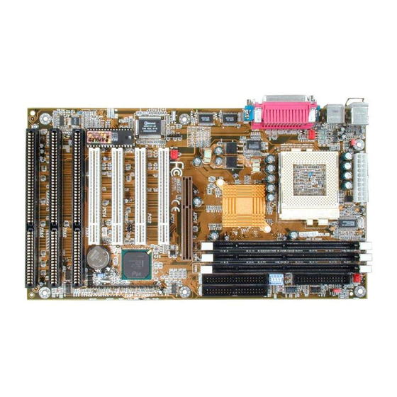
Chapter 2 - Hardware Installation 2.1 System Board Layout... -
Page 12: System Memory
Hardware Installation Warning: Electrostatic discharge (ESD) can damage your system board, processor, disk drives, add-in boards, and other components. Perform the upgrade instruction procedures described at an ESD workstation only. If such a station is not available, you can provide some ESD protection by wearing an antistatic wrist strap and attaching it to a metal part of the system chassis. -
Page 13: Installing The Dim Module
Hardware Installation 2.2.1 Installing the DIM Module A DIM module simply snaps into a DIMM socket on the system board. Pin 1 of the DIM module must correspond with Pin 1 of the socket. Notch Pin 1 1. Pull the “tabs” which are at the ends of the socket to the side. 2. -
Page 14: Dip Switch Settings For Processors
Hardware Installation 2.3 DIP Switch Settings (For Factory Use Only) ™ You can not overclock an Intel Celeron processor (PPGA) because its frequency ratio is fixed by the manufacturer. The table below is for factory use only. In the example on the left: Switch 1: Off Switch 2: On Switch 3: Off... -
Page 15: Jumper Settings For The Cpu's Front Side Bus
Hardware Installation 2.4 Jumper Settings for the CPU’s Front Side Bus Jumper JP2 CPU’s Front Side Bus Select The default setting of jumper JP2 is Auto - the system will automatically run according to the FSB of the processor. The “100MHz” setting (1-2-3 Off) is reserved for future 100MHz FSB processors. -
Page 16: Jumper Settings For Clearing Cmos Data
Hardware Installation 2.5 Jumper Settings for Clearing CMOS Data Jumper JP3 Clear CMOS Data If, for some reason, the CMOS data becomes corrupted or you forgot super visor/user/keyboard password, the system can be reconfigured with the default values stored in the ROM BIOS. To load the default values, power off your system and unplug the power... -
Page 17: Jumper Settings For Wake-On-Keyboard/Mouse
Hardware Installation 2.6 Jumper Settings for Wake-On-Keyboard/ Wake-On-Mouse Jumper JP1 Wake-On-Keyboard/Wake-On-Mouse The system board supports the Wake- On-Keyboard/Wake-On-Mouse function. This function allows you to use the keyboard or mouse to power-on the system. By default, JP1 is disabled. To use this function, set JP1 to 2-3 On. -
Page 18: Connecting The Ribbon Cables And Wires Of The Ports And Connectors
Hardware Installation 2.7 Connecting the Ribbon Cables and Wires of the Ports and Connectors 2.7.1 Serial Ports The built-in serial ports are RS-232C asynchronous communication por ts with 16C550A-compatible UARTs that can be used with modems, serial printers, remote display terminals, and other serial devices. -
Page 19: Parallel Ports
Hardware Installation 2.7.3 Parallel Ports The system board has a standard printer port for interfacing your PC to a parallel printer. It supports SPP, ECP and EPP modes. You can set the port’s mode in the Integrated Periph- erals setup of the Award BIOS. Setting Function Allows normal speed operation... -
Page 20: Ide Hard Disk Interface
Hardware Installation Connecting the Floppy Disk Cable 1. Install 34-pin header connector into the shrouded floppy disk header (J4) on the system board. The colored edge of the ribbon should be aligned with pin 1 of J4. 2. Install the other 34-pin header connector(s) into disk... -
Page 21: Adding A Second Ide Hard Drive
Hardware Installation Connecting the Hard Disk Cable 1. If you are connecting two hard drives, install the 40-pin connector of the IDE cable into the primary shrouded IDE header (connector J10). If you are adding a third or fourth IDE device, install the 40-pin connector of the other IDE cable into the secondary shrouded IDE header (connector J9). -
Page 22: Irda Connector
Hardware Installation 2.7.6 USB Ports You must have the proper drivers installed in your operating system to use these por ts. Refer to your operating system’s manual documentation. 2.7.7 IrDA Connector The system board is equipped with an IrDA connector for wireless connectivity between your computer and peripheral devices. -
Page 23: Cpu Fan Connector
Hardware Installation 2.7.8 CPU Fan Connector The processor must be kept cool by using a fan with heatsink. Connect the CPU fan to the 3-pin fan connector at location J5 on the system board. Function On/Off +12V Sense 2.7.9 Chassis Fan Connector The system board is equipped with a chassis fan connector. - Page 24 Hardware Installation 2.7.10 AGP Fan Connector The system board is equipped with an AGP fan connector. If the system board is installed with an AGP add-in card and you wish to install a fan on the add-in card, connect the fan’s connector to location J11 on the system board.
- Page 25 Hardware Installation 2.7.12 Wake-On-LAN Connector The system board suppor ts the Wake-On-LAN function. This function will allow the network to remotely power-on a Soft Power Down (Soft-Off) PC. However, if your system is in the Suspend mode, you can power-on the system only through an IRQ or DMA interrupt.
-
Page 26: Power Connector
Hardware Installation 2.7.13 Power Connector The pin assignment of the ATX power connector is shown below. Function Function 3.3V/14A 3.3V/14A 3.3V/14A -12V PS-ON PW-OK 5VSB +12V Important: Your power supply must meet the ATX specification - supporting 3.3V/14A (minimum), otherwise your system will not boot properly. - Page 27 Hardware Installation 2.7.14 J14 (LEDs and Switches) HD-LED: Primary/Secondary IDE LED This LED will light when the hard drive is being accessed. G-LED: Green LED This LED will light when the system is in the Suspend mode. ATX-SW: ATX Power Switch Depending on the setting in the BIOS setup, this switch is a “dual function power button”...
- Page 28 Hardware Installation KEYLOCK: Power/Standby LED and Keylock Connector Use pins 21-23 to connect to the Power/Standby LED. This LED will light when the system’s power is on and blinks when the system enters the Suspend mode. Use pins 24 to 25 to connect to the keyboard lock (located on the front panel of the system chassis) for locking the keyboard.
-
Page 29: Chapter 3 - Award Bios Setup Utility
Chapter 3 - Award BIOS Setup Utility 3.1 The Basic Input/Output System The Basic Input/Output System (BIOS) is a program that takes care of the basic level of communication between the processor and peripherals. In addition, the BIOS also contain codes for various advanced features found in this system board. -
Page 30: Award Bios Setup Utility
Award BIOS Setup Utility ROM PCI/ISA BIOS STANDARD CMOS SETUP AWARD SOFTWARE, INC. Date (mm:dd:yy) : Mon, Oct 12 1998 Time (hh:mm:ss) : 13: 27: 50 HARD DISKS TYPE SIZE HEAD CYLS PRECOMP LANDZ SECTOR MODE Primary Master Auto Auto Primary Slave Auto Auto... - Page 31 Award BIOS Setup Utility Drive A and Drive B These categories identify the types of floppy disk drives installed. None No floppy drive is installed 360K, 5.25 in. 5-1/4 in. standard drive; 360KB capacity 1.2M, 5.25 in. 5-1/4 in. AT-type high-density drive; 1.2MB capacity 720K, 3.5 in.
-
Page 32: Bios Features Setup
Award BIOS Setup Utility 3.1.2 BIOS Features Setup The BIOS Features Setup allows you to configure your system for basic operation. Some entries are defaults required by the system board, while others, if enabled, will improve the performance of your system or let you set some features according to your preference. - Page 33 Award BIOS Setup Utility CPU L1 Cache and CPU L2 Cache These categories speed up the memory access. The default value is enabled. Enable the External Cache for better performance. CPU L2 Cache ECC Checking Intel Celeron processors come with built-in Level 2 cache. By default, ECC is enabled to check the Level 2 cache.
- Page 34 Award BIOS Setup Utility Boot Up NumLock Status This allows you to determine the default state of the numeric keypad. By default, the system boots up with NumLock on wherein the function of the numeric keypad is the number keys. When set to Off, the function of the numeric keypad is the arrow keys.
-
Page 35: Chipset Features Setup
Award BIOS Setup Utility OS Select for DRAM > 64MB This item allows you to access the memory that is over 64MB in OS/2. The options are: Non-OS/2 and OS/2. HDD S.M.A.R.T. Capability The system board supports SMART (Self-Monitoring, Analysis and Reporting Technology) hard drives. - Page 36 Award BIOS Setup Utility any changes would be if you discovered some incompatibility or that data was being lost while using your system. SDRAM RAS-to-CAS Delay This field allows you to insert a timing delay between the CAS and RAS strobe signals, used when DRAM is written to, read from, or refreshed.
- Page 37 Award BIOS Setup Utility Video RAM Cacheable When enabled, it allows the video RAM to be cacheable thus providing better video performance. If your graphics card does not support this function, leave this field in its default setting - Disabled. 8 Bit I/O Recovery Time and 16 Bit I/O Recovery Time The recovery time is the length of time, measured in SYSCLK, which the system will delay after the completion of an input/output request.
- Page 38 Award BIOS Setup Utility at the same time appear next to the external bus clock selected. For example, if you selected "66.8/33.4", 66.8MHz is the external bus clock and 33.4MHz is the PCI clock. Regardless of the type of pro- cessor used, the default setting is "Default".
-
Page 39: Power Management Setup
Award BIOS Setup Utility • Current System Temperature, Current CPU Temperature, Current Chassis Fan Speed and Current CPU Fan Speed These fields show the internal temperature of the system, current temperature of the processor, and the current fan speed of the chassis and CPU fans in RPM (Revolutions Per Minute). - Page 40 Award BIOS Setup Utility ACPI Function By default, the ACPI function is disabled. This function should be enabled only in operating systems that support ACPI. Power Management This category allows you to select the type (or degree) of power saving by changing the length of idle time that elapses before the Standby mode and Suspend mode are activated.
- Page 41 Award BIOS Setup Utility Standby The screen is off when the system is in the Standby mode. MODEM Use IRQ This category is used to set an IRQ channel (IRQ 3, 4, 5, 7, 9, 10 or 11) for the external modem installed in your system. However, if the “Resume on Ring”...
- Page 42 Award BIOS Setup Utility Hold 4 Sec. Regardless of whether the Power Management field is enabled or disabled, if the power button is pushed and released in less than 4 sec, the system enters the Suspend mode. The purpose of this function is to prevent the system from powering off in case you accidentally “hit”...
- Page 43 Award BIOS Setup Utility 7. Press <Esc> to return to the main menu of the Award BIOS setup utility. Select “Save & Exit Setup” and press <Enter>. 8. Type <Y> and press <Enter>. Resume On LAN With a LAN card installed, the Wake-On-LAN function allows the network to remotely wake up a Soft Power Down (Soft-Off) PC.
-
Page 44: Pnp/Pci Configuration
Award BIOS Setup Utility 3.1.5 PNP/PCI Configuration This section describes configuring the PCI bus system. It covers some ver y technical items and it is strongly recommended that only experienced users should make any changes to the default settings. ROM PCI/ISA BIOS PNP/PCI CONFIGURATION AWARD SOFTWARE, INC. -
Page 45: Load Fail-Safe Settings
Award BIOS Setup Utility Assign IRQ for VGA When Enabled, the system automatically assigns an IRQ for the VGA card installed. Your VGA card will need an IRQ only when using the video capture function of the card. If you are not using this function and a new device requires an IRQ, you can set this function to Disabled. -
Page 46: Load Optimal Settings
Award BIOS Setup Utility 3.1.7 Load Optimal Settings The “Load Optimal Settings” option loads optimized settings from the BIOS ROM. Use the Setup default values as standard values for your system. Highlight this option on the main menu and press <Enter>. The message below will appear. - Page 47 Award BIOS Setup Utility themselves. Your system supports five modes, 0 (default) to 4, which primarily differ in timing. When Auto is selected, the BIOS will select the best available mode after checking your drive. Auto The BIOS will automatically set the system according to your hard disk drive’s timing.
- Page 48 Award BIOS Setup Utility Onboard FDC Controller Enabled Enables the onboard floppy disk controller. Disabled Disables the onboard floppy disk controller. Onboard Serial Port 1 and Onboard Serial Port 2 Auto The system will automatically select an I/O address for the onboard serial port 1 and serial port 2.
- Page 49 Award BIOS Setup Utility Parallel Port Mode, ECP Mode Use DMA and EPP Mode Select These fields will appear only if you selected an I/O address and IRQ in the Onboard Parallel Por t field. These apply to a standard specification and will depend on the type and speed of your device.
-
Page 50: Supervisor Password
Award BIOS Setup Utility Hot Key When this option is selected, the “KB Power On Hot Key” field will appear. Move the cursor to this field to select a function key you would like to use to power- on the system. The options are from Ctrl-F1 to Ctrl- F12. -
Page 51: User Password
Award BIOS Setup Utility 3.1.10 User Password If you want another user to have access only to your system but not to setup, set a user’s password with the “System” option selected in the BIOS Features Setup. If you want a user to enter a password when trying to access setup, set a user’s password with the “Setup”... -
Page 52: Save & Exit Setup
Award BIOS Setup Utility 3.1.12 Save & Exit Setup When all the changes have been made, highlight “Save & Exit Setup” and press <Enter>. The message below will appear: Save to CMOS and Exit (Y/N)? N Type “Y” and press <Enter>. The modifications you have made will be written into the CMOS memory, and the system will reboot. -
Page 53: Chapter 4 - Supported Softwares
Chapter 4 - Supported Softwares 4.1 Desktop Management Interface (DMI) The system board comes with a DMI built into the BIOS. DMI, along with the appropriately networked software, is designed to make inventory, maintenance and troubleshooting of computer systems easier. With DMI, a network administrator or MIS engineer can remotely access some information about a particular computer system without physically going to it. -
Page 54: Supported Softwares
Supported Softwares 4.1.2 Using the DMI Utility Award DMI Configuration Utility Copyright Award Software Inc, 1996 [Edit DMI] [Add DMI] [Load DMI File] [Save DMI File] BIOS *** BIOS Auto Detect *** System Enclosure/Chassis Type : BIOS Information... - Page 55 Supported Softwares Add DMI 1. Use the ← or → arrow keys to select the Add DMI menu. 2. Highlight the item on the left screen that you would like to add by using the ↑ or ↓ arrow keys, then press <Enter>. 3.
-
Page 56: Hardware Doctor Utility
Supported Softwares 4.2 Hardware Doctor Utility The system board comes with a Hardware Doctor utility contained in the provided CD. This utility is capable of monitoring the system’s “health” conditions and allows you to manually set a range (Highest and Lowest Limit) to the items being monitored. If the settings/ values are over or under the set range, a warning message will pop- up. - Page 57 Supported Softwares The rightmost column of the screen shows the current value of each monitored item. To set the highest and lowest limit of each item, click on the arrow buttons in the “Lowest Limit” or “Highest Limit” column. However, we DO NOT recommend that you change the settings of the Voltages.
-
Page 58: Patch Utility For Windows 95
Supported Softwares Beep Besides the pop-up warning message, you can choose to enable the beep alarm so that if an abnormal condition occurs, an alarm will sound. Due to its hardware limitation, the only item that cannot be enabled is “System Temp”. If the internal temperature of the system is too high, only a warning message will pop-up. - Page 59 Appendix A - System Error Message When the BIOS encounters an error that requires the user to correct something, either a beep code will sound or a message will be displayed in a box in the middle of the screen and the message, PRESS F1 TO CONTINUE, CTRL-ALT-ESC or DEL TO ENTER SETUP, will be shown in the information box at the bottom.
- Page 60 System Error Message setting than indicated in Setup. Determine which setting is correct, either turn off the system and change the jumper or enter Setup and change the VIDEO selection. FLOPPY DISK(S) fail (80) Unable to reset floppy subsystem. FLOPPY DISK(S) fail (40) Floppy type mismatch.
- Page 61 Appendix B - Troubleshooting B.1 Troubleshooting Checklist This chapter of the manual is designed to help you with problems that you may encounter with your personal computer. To efficiently troubleshoot your system, treat each problem individually. This is to ensure an accurate diagnosis of the problem in case a problem has multiple causes.
-
Page 62: Troubleshooting
Troubleshooting The picture seems to be constantly moving. 1. The monitor has lost its vertical sync. Adjust the monitor’s vertical sync. 2. Move away any objects, such as another monitor or fan, that may be creating a magnetic field around the display. 3. -
Page 63: Hard Drive
Troubleshooting Hard Drive Hard disk failure. 1. Make sure the correct drive type for the hard disk drive has been entered in the BIOS. 2. If the system is configured with two hard drives, make sure the bootable (first) hard drive is configured as Master and the second hard drive is configured as Slave. -
Page 64: Serial Port
Troubleshooting Serial Port The serial device (modem, printer) doesn’t output anything or is outputting garbled characters. 1. Make sure that the serial device’s power is turned on and that the device is on-line. 2. Verify that the device is plugged into the correct serial port on the rear of the computer.
Need help?
Do you have a question about the GCB60-BX and is the answer not in the manual?
Questions and answers