
Summary of Contents for TEM A07A2200S
- Page 1 A07A2200S TECHNICAL , MAINTENANCE AND INSTALLATION MANUAL 2000 W FM TRANSMITTER A07A2200S 380221...
- Page 2 A07A2200S ACCORDING TO R&TTE RULES NOTIFIED BODY : 0523 All rights are strictly reserved Reproduction or issue to third parties in any form whatever is not permitted without written authorization 380 221 R02 Pag. 2...
-
Page 3: Table Of Contents
Index CHAPTER 1 : Safety Instructions pag.5 CHAPTER 2 : Electrical Specifications pag.7 CHAPTER 3 : General Description pag.10 CHAPTER 4 : Installation & Transmitter Setting pag.14 CHAPTER 5 : Circuit Description pag.30 CHAPTER 6 : Modulation Measurement pag.37 CHAPTER 7 : Remote Control pag.43 CHAPTER 8 : Internal Adjustment &... - Page 4 pag.68 CHAPTER 12 : RF Detector CHAPTER 13 : Driver Exciter pag.70 CHAPTER 14 : Power Supply pag.71 CHAPTER 15 : Switch Front Pannel pag.76 CHAPTER 16 : AUDIO IN Board pag.77 CHAPTER 17 : DLCD Board pag.83 CHAPTER 18 : MBA Board pag.88 CHAPTER 19 : SINTD Board pag.95...
-
Page 5: Chapter 1 : Safety Instructions
A07A2200S SAFETY INSTRUCTIONS Introduction T.E.M. has always managed to improve the safety standard if its transmitting and receiving equipment. All produced systems are tested in compliance with international EN60950 and EN60215 rules. Obviously this is not sufficient to avoid any accident during the installation and the use of our equipment in compliance with EN60215 rule, the radio transmitters and the auxiliary equipment must be used by qualified technical staff only and T.E.M.. - Page 6 A07A2200S WARNING SEVERAL SYMBOLS, INSIDE THE TYPICAL TRIANGLE SHOWING DANGER, HAVE BEEN PRINTED ON SEVERAL TRANSMITTER PARTS. ATTENTION SHOULD BE PAID, BECAUSE THERE COULD BE THE DANGER DUE TO HOT SURFACES, ELECTRIC VOLTAGE HIGHER THAN 50VOLT OR OTHER SPECIFIED DANGERS.
-
Page 7: Chapter 2 : Electrical Specifications
A07A2200S A07A2200S FM BROADCASTING TRANSMITTER ELECTRICAL SPECIFICATION FREQUENCY - POWER Frequency range ------------------------------------------------------------------------------ 87.6 to 107.9MHz Frequency setting ------------------------------------------------------------------------------------ 10 Khz steps Internal setting mode -------------------------------------------------------------------------------------- by keys External setting mode --------------------------------------------------- by remote control ( RS232-RS485 ) Frequency stability ----------------------------------------------------------------------------------±250Hz/year... -
Page 8: Remote Control
A07A2200S CHARACTERISTICS IN STEREO Signal inputs------------------------------------------------------------------------------------------Left or Right Input impedance --------------------------------------------------------------------- 600? (balanced) or 10k? Unbalance rejection ----------------------------------------------------------------------------------------->40dB Input level------------------------------------------------------------------------------------------- –6 to +12dBm Pre-emphasis --------------------------------------------------------------------------------------------75 or 50? s Audio frequency response (30Hz to 15KHz)--------------------------------------------------------- <0.15dB Audio frequency response (19KHz to 100KHz) --------------------------------------------------------<40dB Cross-talk between left and right channel --------------------------------------------------------------->50dB... - Page 9 A07A2200S POWER SUPPLY AND TEMPERATURE RANGE Operating voltage ---------------------------------------------------------------------------------230V ±15 % Operating voltage(option)-----------------------------------------380V ±10 % Three phases + Neutral Line power ------------------------------------------------------------------------------------------------<3800VA Nominal temperature range ----------------------------------------------------------------------- - -5° to 45°C Operating temperature range---------------------------------------------------------------------- -10° to 50°C Storage temperature range------------------------------------------------------------------------- -40° to 50°C MECHANICAL SPECIFICATION 19”...
-
Page 10: Chapter 3 : General Description
A07A2200S GENERAL DESCRIPTION Main features A07A2200S is a FM band broadcasting transmitter with modern conceiving and technology, which by a simple design produces an output radio signal with high characteristics of quality, reliability and security. The simple manufacturing obtained with a hi integration of functions, has allowed to create a machine with few controls and connections. -
Page 11: Available Options
A07A2200S Besides the keyboard, the transmitter can be remotely controlled in different ways. A personal computer can be connected as monitor to the DB9 socket placed on the front panel and by a special program, to be load easily on the PC, all the transmitter parameters can be set and seen. - Page 12 A07A2200S The mono signal or the stereo one, thus obtained, is combined with the other three possible input audio signals: an external Multiplex signal and two SCA signals, one of which can be the RDS one, which can be synchronized with a 19KHz one connected on the IN/OUT rear connector.
- Page 13 A07A2200S A07A2200S BLOCK DIAGRAM 380 221 R02 Pag. 13...
-
Page 14: Unpacking And Inspection
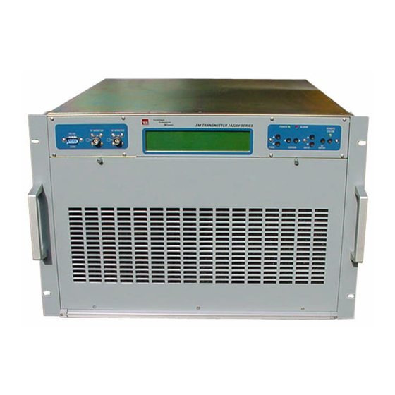
Installation The transmitter A07A2200S is composed of a 19 inches width rack which takes 7 units in height in a vertical rack mount. It is recommended to use 4 fixing plastic washers in order to avoid damages to the front panel varnishing. - Page 15 A07A2200S Ground loops Sometimes connecting various ground sockets having different potentials may produce some unwanted loops, which may create hum in the modulation: in this case it is essential to firstly identify the origin of these currents, which normally spring from the antenna ground, mains supply ground or from the input low frequency signals ground.
- Page 16 A07A2200S 07A2200 T.E.M. S.p.A. T.E.M T.E.M 4.6.2 Afterwards another page will appear for few seconds allowing to change the mains supply voltage value; the value setting operation to 230V , allows the transmitter to operate correctly, but it doesn't allow the microprocessor controlling the equipment to know the mains supply voltage value.
- Page 17 A07A2200S 2000 GSM > ON NO ALARMS I/O -> ON The display is explanatory enough FREQUENCY is the output frequency set in MHz FORW. PW is the forward output RF power REFL. PW is the input reflected power on the RF connector...
- Page 18 A07A2200S CARRIER EN shows if the output power is enabled either by a keyboard command or by an external command through the IN/OUT rear connector. PA VOLTAGE is the supply voltage of the RF power final mosfet. PA CURRENT is the voltage drained by the mosfet final power.
- Page 19 A07A2200S 4.6.6 The screen shot for the password request is the following: To go on, it is essential entering the four numbers which can be known by reading the transmitter delivery document. If the password is unknown or it is too difficult to open the top cover by unscrewing the 20 locking screws, it is just possible to surf among the previous screen shots which give all the information about the transmitter.
- Page 20 A07A2200S In this screen shot, like in the previous one, it’ s possible to set the higher limit of the allowed maximum reflected power. If the set limit tends to be exceeded, for a bad antenna operation or a bad load connected to the RF connector, the direct power is reduced proportionally so that this limit won't be exceeded, thus protecting the RF power final mosfet.
- Page 21 A07A2200S 4.6.10 By entering PAGE UP the following screen shot is accessed : In this screen shot the output frequency can be set by the usual cursors with a resolution of 10KHz. On the display the current frequency and the new value appear.
- Page 22 A07A2200S 4.6.12 PAGE UP for a new screen shot : In this case it’ s possible to insert the pre-emphasis or to set the transmitter from mono to stereo and vice versa. The pre-emphasis value (50 or 75µs) is switched by a jumper placed on the rear window of the rack.
- Page 23 A07A2200S By modulating the transmitter through the nominal level input signals and with fixed tone (i.e.. 400Hz), the deviation must not exceed 75KHz (COMP) and the input signal level must not exceed 100%. But if a music signal is available at the input, indication can also exceed this value and the exact rules for this check will be seen in the screen shot 11.
- Page 24 A07A2200S 380 221 R02 Pag. 24...
- Page 25 A07A2200S The previous eight screen shots, if selected, allow to perform the measurement of the modulation analysis according to the CEPT 54-01rule. For an exhaustive explanation of this new measurement method see chapter 7. Briefly, it can be said that a music signal can exceed the limit threshold of 75kHhz, provided that this exceeding is contained in a certain percentage.
- Page 26 A07A2200S compared to the one equivalent to a sine signal which deviates 19KHz; the result of the comparison is expressed in dB and it must not be higher than 0, in order to make the measurement complying with the rule. This limit is debatable and, as it has been described in chapter 7, normally in on-field measurements the values of 2,3dB are found which, after all, we estimate don’...
- Page 27 A07A2200S NUMBERS SETTING FOR SMS SEND… … … .. GSM 1 = … … … … … … … … … … … … … ... (SENT = 0) GSM 2 = … … … … … … … … … … … … … ...
-
Page 28: Chapter 5 : Circuit Description
A07A2200S CIRCUITS DESCRIPTION AUDIO-IN board The AUDIO-IN board has the task to interface the input audio signals with the modulator. Level adjustments are performed on them, as well as pre-emphasis insertion and input impedance selection. The outputs, going through a flat-cable to the mother board, are raised to a high level and made balanced in order not to be interfered with the transformer flow dispersion. - Page 29 A07A2200S SINTD board SINTD board is placed at the rack centre, directly connected to the mother board from which it can be quickly removed. It has the function of frequency synthesized oscillator (88 – 108MHz) modulated by the audio composite signal.
- Page 30 A07A2200S MBA board The central board has the task to distribute the power sup plies and the input and output signals; moreover, the audio filters and the peak-to-peak detector for the different modulation level measurements are implemented in it. Both the left and the right channel signals coming from the AUDIO-IN board through the J7 connector, pass through an elliptic filter made of precision active components;...
- Page 31 A07A2200S On the board it’ s possible to activate an alarm signal which takes place when the modulation is lower than 10KHz for a period of time longer than two minutes (the level 10KHz has been selected because is a little higher than the value due to the stereo subcarrier). When the modulation absence alarm is on, the output power is removed and the transmitter remains in stand-by until the modulation will be restored.
- Page 32 A07A2200S MBA module - mother board On the mother board it’ s possible to perform the modulation width setting, of the stereophonic coded signal levels, the automatic check gain regulation threshold, and the phase compensation and the multiplex signal width.
- Page 33 A07A2200S Inject a 400Hz signal and +6dBm level in the LEFT input, switch into STEREO and adjust RT7 of the MBA board to read still 75KHz deviation also for MPX channel. Adjust also RT1 if the subcarrier deviation at 19KHz is not the 10% of the total and adjust again the previous RT7 trimmer.
- Page 34 A07A2200S Adjust the RT6 trimmer of the MBA board to fix the clipper intervention threshold at the required value over 75KHz. Adjust the RT1 trimmer of the synthesis board to have the exact frequency deviation with the input nominal level presence.
-
Page 35: Chapter 6 : Modulation Measurement
A07A2200S MODULATION MEASUREMENT General information The broadcast reception at frequency modulation is often made difficult because of the networks exceeding crowding; the interferences due to the adjacent channels makes the listening unpleasant. This inconvenient may be caused by an ignoring of the protection rules mentioned in the REC. ITU... - Page 36 A07A2200S with coloured noise as mentioned in the CCIR 559 rule (annex B). The process is described in the IEC 244-13 standard and consists of modulating the transmitter with noise as above, with a deviation equal to 32KHz. This work condition corresponds to the maximum allowed band occupation and to a radio broadcast spreading dance-music which modulates ±75KHz.
- Page 37 A07A2200S Now, instead of these simple examples, take our transmitter modulated with the sample noise previously mentioned, and we detect in accordance with the CEPT 54-01 the modulation peak samples in a 30 minutes observation period, so obtaining the graph. 5.c-a whereas, if we increase the modulation, always with the same input signal, of 1dB, we’...
- Page 38 A07A2200S In the figures 5.c-b and 5.d-b, as suggested by CEPT 54-01, the “Accumulated distribution plot of deviation“ have been reported on the graph, relating to the graphs of the left figures -a and -b ; in this case all the samples from left to right have been added and the samples total value has been normalized.
- Page 39 A07A2200S fig. 5.e fig. 5.f Examine the graphs of. 5.e, which could correspond to the modulation peak analysis of a regular transmitter which doesn’ t over modulate: in these each minute M, OM, OM% values have been 380 221 R02...
- Page 40 A07A2200S calculated and consequently the K factor. It can be noticed that K value constantly keeps each minute below the value 0.01. So assume this value as limit for the over modulation factor. Increasing the modulation of 1dB the graphs in fig. 5.f are given, corresponding to a transmitter which deviates little more than ±8KHz;...
- Page 41 A07A2200S calculation is to be made by the integral which defines the power. Besides the modulation power value in absolute form would be of a difficult understanding, for this reason any sinusoidal signal is taken as reference whose power, for long observation periods, doesn’ t depend on the sinusoid frequency but only on its peak value square.
- Page 42 A07A2200S is switched off. Next, a noise signal C+D replaces the sinusoidal tone, and attenuator E is adjusted to obtain the same peak-reading as before at the noise voltmeter. The quasi peak deviation is thus equal to 32 KHz. Since the pre...
-
Page 43: Chapter 7 : Remote Control
A07A2200S Adjust the output of the LF generator at <1KHz to a level corresponding to a frequency deviation of 40 KHz including pilot tone. Measure the peak value in channel B after the demodulator and stereo encoder by means of the noise meter (without the weighting network ). - Page 44 A07A2200S DT 100 FM Broadcasting Transmitter DT 100 T.E.M. The screen cursor which displays the modulation will be still and the low left inscription RS232 Connection will show: not connected. At this point it is essential, after the transmitter has been switched on, to make it communicate.
- Page 45 A07A2200S The first page is just an introduction to the system, of which it’ s possible to know the options installed or the hour of the last switching on. At the right bottom of the display there is a grey window with an arrow and if it is entered it’...
- Page 46 A07A2200S “Channel Modulation“, the respective changes will be displayed on the higher window too. When the chosen data are the requested ones it’ s possible to switch the red button off and the normal displaying will be restored. Selecting the fourth page the power settings are entered: DT 100 FM Broadcasting Transnmitter Here also the settings are distinguished from the measurements by a different colour.
- Page 47 A07A2200S DT 100 FM Broadcasting Transmitter Here the transmitter clock settings and frequencies can be changed. Differently from the previous pages, here the variations cannot be performed in real time, to avoid the transmitter goes on unwanted frequencies. So, at first data must be inserted then the red button must be pressed to enter them.
- Page 48 A07A2200S The quantities controlled by this function are: MAINS SUPPLY VOLTAGE CURRENT ON THE RF FINAL VOLTAGE ON THE RF FINAL RF FINAL RADIATOR TEMPERATURE MODULATION ABSENCE SYNTHESIZED OSCILLATOR ANOMALOUS OPERATING EXTERNAL CARRIER ENABLE Whenever the limits joined to each quantity mentioned above are exceeded, the output power is taken off, a visual signalling and ON/OFF contacts are given and the event is stored and associated to the date when it has occurred.
- Page 49 A07A2200S DT 100 FM Broadcasting Transmitter As appendix the whole theory concerning this kind of measurements is dealt in chapter 7, dedicated to the modulation measurements. In the upper graphs the peak modulation statistic parameters of a broadcast network observed during 10 minutes period are reported. It can be observed that the 12000 peak measurement samples detected lead to consider that the network is on the limit of the allowed deviation;...
-
Page 50: Chapter 8 : Internal Adjustment & Settings
A07A2200S A07A2200S INTERNAL ADJUSTMENTS & SETTINGS See figg. 9.a for function number Board name/ FUNCTION DESCRIPTION N° Component MPX freqquency Adjust, with nominal MPX input level, for 75 Khz MBA/RT7 deviation frequency deviation 1 DMPX/C22 Pilot frequency Adjust stereo subcarrier to 19 Khz +/-1Hz... - Page 51 A07A2200S Fig. 9.a 380 221 R02...
-
Page 52: Chapter 9 : Rear Connections & Settings
A07A2200S A07A2200S REAR CONNECTIONS & SETTINGS See fig. 9.d for function number N° FUNCTION CONNECTION KEYBOARD DISPLAY RX ( amplifier ) TX ( amplifier ) COM2 NUMBER RS232 to power amplifier ( DB9 ) RF MONITOR BF MONITOR AUX IN/OUT... - Page 53 A07A2200S N° FUNCTION CONNECTION INPUT RS485 + INPUT RS485 - COM3B NUMBER RS485 to N+1 system ( DB9 ) +8V (Opt remote Zarat) Remote State Trimmer RT5 / AUDIO IN board EXTERNAL MONO / MPX ± 2 dB adj. ref to nominal value set for 75 Khz modulation...
- Page 54 A07A2200S REMOTE AC MAINS INPUT 380 221 R02...
-
Page 55: Connection Diagram
A07A2200S CONNECTION DIAGRAM Tecnologie Elettroniche Milanesi FM TRANSMITTER 7A2200 SERIES POWER ALARM REMOTE 232/485 PAGE CURSOR DATA ENTER Tecnologie Elettroniche Milanesi FM TRANSMITTER 7A2200 SERIES POWER ALARM REMOTE 232/485 RF MONITOR BF MONITOR RS 232 COM1 PAGE CURSOR DATA ENTER fig. - Page 56 A07A2200S Right Left MONO µ µ +12 dBm SCA 1 +6 dBm +4 dBm 0 dBm SCA 2 LEFT RIGHT ALARMS AUX I/O RS 485 A MON O µ FUSES µ REMOTE RS 485 B SCA 1 +12 dBm +6 dBm...
- Page 57 JR 5- 6- 7- 14 JC 10 JC 15 13M 7A U D I O I N JC 13 A udi o I nput Tr ansf or m er JC 9 D W G 32938 JC 12 R F O ut put 13M 7M B A M ot her - B oar d 13M 30140...
- Page 58 Lat er al vi ew Top vi ew C O N 10 18 V Ar anci o 1, 5 A 230V 18 V F101 0, 6 A 220V N er o 3014 1, 5 A 15 V J102 0, 5A Bi anco J101 Equi pm ent...
- Page 59 R G 316 JR 1 = 280 m m B N C 24C 00205 18B 00260 f em al e connect or 24x03710 JR 2 = 340 m m 90° B N C R G 403 SM A 18B 00290 24A 00025 24C 00445 SM B 24B 00165...
- Page 60 Pi n 1- 1 Pi n N - N Pi n 1- 1 Si de N - N Pi n C l ouse JC 5= 26 Pi n 480 m m JC 9= 26 Pi n 260 m m D i spl ay 24x02700 JC 1= 26 Pi n...
- Page 61 R.F. Amp. 1 R.F. Wilkinson Divider. 600 W R.F. Wilkinson Combiner 15 W 48V 20A Power Supply 15 W R.F. Amp. 2 600 W RF Output 30 W 48V 20A Forward 60 W R.F. Filter RF Input Power Supply 2 dB Output 88-108 MHz Reflected...
- Page 62 Az.:001 TEM 26/01/2007 09:16 Pag. Codice Distinta: 13M72240 MODULO RF 2KW FM Livello Componenti Quantità Produttore Descrizione Riferimenti Schema 0 13M72240 MODULO RF 2KW FM 1 13M30101 RF INPUT 2 KW FM COST REDUCTION 03-2006 1,00 TEM C 001 - C 005...
- Page 63 Az.:001 TEM 26/01/2007 09:16 Pag. Codice Distinta: 13M72240 MODULO RF 2KW FM Livello Componenti Quantità Produttore Descrizione Riferimenti Schema J 007 2 24A00465 SMA C.S. FEMM. 82SMA-50-0-1 1,00 SHUNER J 008 2 24X03370 CONN M CS 43650-0215 2PIN MICRO FIT 3.0...
- Page 64 Az.:001 TEM 26/01/2007 09:16 Pag. Codice Distinta: 13M72240 MODULO RF 2KW FM Livello Componenti Quantità Produttore Descrizione Riferimenti Schema VR 01 2 22A01040 NTC (FIL.M3) K45/2,2K 10% 191-215 1,00 EPCOS ZA 01 2 44Z00010 ZOCCOLO x INTEGRATO 8-pin CICO-083-S8A- 5,00 R.N.
- Page 65 Az.:001 TEM 26/01/2007 09:16 Pag. Codice Distinta: 13M72240 MODULO RF 2KW FM Livello Componenti Quantità Produttore Descrizione Riferimenti Schema C 017 - C 026 - C 093 - C 101 2 CACTE50033100N COND.CER.CHIP HQ-B 10pF 500V 4,00 TEKELEC C 018...
- Page 66 +48V1A C 155 C 158 I N D C 157 C 226 C 225 C 156 330u 330u M R 852 D I R +48V1B R I F C 161 C 160 C 159 I N D +15V C 224 1u C 162 C 223 I C 1B...
- Page 67 R 044 470R BP FI LTER R 10 2KW R F O U T R 144 100n R F O UT R V1 330p 1000p 1000p N TC 2 4sp d. 10 BLF278 G 3026/ 27 C 259 L101 f i l o 1. 5m m R B11 4sp.
- Page 68 R 48 R 56 C 79 R 146 100n 1K 5 C 80 C 77 R V5 N TC 6 2K 2 330p 1000p C 81 1000p 4sp d. 10 B LF278 G 3026/ 27 C 271 R 50 f i l o 1. 5m m P ont .
- Page 69 Az.:001 TEM 26/01/2007 09:17 Pag. Codice Distinta: 13M30280 RF OUT 2 KW FM STRIPLINE Livello Componenti Quantità Produttore Descrizione Riferimenti Schema 0 13M30280 RF OUT 2 KW FM STRIPLINE 1 13M30311 USCITA STRIPLINE PER ALIM. 2 KW COST RED 1,00 TEM...
- Page 70 C 140 C 124 C 108 C 82 C 65 C 49 C 33 C 34 C 66 C 141 C 50 C 83 C 109 C 125 C 93 C 26 C 17 C 101 C 261 C 258 C 260 C 259 C 153...
- Page 71 Az.:001 TEM 26/01/2007 09:18 Pag. Codice Distinta: 13M30100 RF INPUT 2 KW FM Livello Componenti Quantità Produttore Descrizione Riferimenti Schema 0 13M30100 RF INPUT 2 KW FM C 001 - C 005 - C 028 - C 032 - C 044 1 CACTE05033100L COND.CER.CHIP HQ 1000pF 50V...
- Page 72 Az.:001 TEM 26/01/2007 09:18 Pag. Codice Distinta: 13M30100 RF INPUT 2 KW FM Livello Componenti Quantità Produttore Descrizione Riferimenti Schema L 009 - L 011 - L 014 - L 036 - L 045 1 29AO9770 BOBINA SP. 977 7,00 TEM...
- Page 73 Az.:001 TEM 26/01/2007 09:18 Pag. Codice Distinta: 13M30100 RF INPUT 2 KW FM Livello Componenti Quantità Produttore Descrizione Riferimenti Schema *** Fine Stampa ***...
- Page 74 R 115 R 114 R 112 C 208 R 107 R 106 R 104 C 193 R 99 R 98 R 96 C 178 R 91 R 90 R 88 C 163 C 211 C 381 C 196 C 371 C 181 C 361 C 166...
-
Page 75: Chapter 11 : Rf Filter
Output Reflected Forward Input L Filter Input Output Forward Reflected 6385 7 mm Input Output Filo argentato 1 mm Reflected Forward cs 3009 Bottom 6386 7 mm Equipment Description 13M30090 RF Filter Parts Placement Scale Sheet Approved Code Edit. 32944 13M30090 Size Sheets... -
Page 76: Chapter 12 : Rf Detector
+15V +15V 220R 100n IC1B IC1A LM358 LM358 P.DIR P.REF HSMS2800 100R +15VE -15VE 330R 390R 390R 330R 2K49 FLAT10 100n HSMS2800 2K49 -15V -15V -15V +15V +15V +15V +15VE 220R 100n IC2B IC2A LM358 LM358 -15V -15VE HSMS2800 100R 330R 390R 390R... - Page 77 Equipment Description 13M30130 Parts Placement 2 KW RF Detector Scale Sheet Drawn Edit. Code Mrn-Mrz 32883 Approved Size Sheets File P.C.Board Date 3-2-2003 3013...
-
Page 78: Chapter 13 : Driver Exciter
Vcontrol 820R 220R 100u 100n VASC10 100n 6,8uH 8sp d7 filo 0,8 180p 3sp d5 filo 0.8 470R BFQ68 180p 3sp d7 filo 0.8 JA1-Teflon JA1-Teflon Equipment Description Parts Placement Driver exciter 2 KW FM Scale Sheet Drawn Edit. Code Mrn-Mrz 13M30150 32932... -
Page 79: Chapter 14 : Power Supply
7818 RELE'12V-16A PONTE 470u 400V 100R 500p 220R 2W BYW51-100 JUMPER TORO TRAFO AUX RS 220R 2W IRFP460 Font panel 30ETH06-1 PONTE IRFPS37N50A BYR29F 0R47 2W 100R FUSE 8A 220R 2W 100R AC IN AC IN BYW51-100 N.M. ETD59 VDR4 0R47 2W 470u 470u... - Page 80 Saldare Maschio 3 Pin Passo 2,54mm Femmina 3 Pin Femmina 2 Pin Passo 2,54mm Passo 2,54mm Eliminare Grasso Silicone (senza isolante) Fili 1,5 mmQ Intrecciati Blù Nero Giallo verde ACIN ACIN Fascetta Fascetta Fascetta Centrale Centrale Centrale Isolato +Colla Isolato +Colla +Colla VDR2...
- Page 81 KBU604 7815 +15V VK200 2200u 2200u 220u 1N4004 KBU604 7915 -15V VK200 D101 D102 2200u 220u CON10 KBU604 7805 VK200 2200u 220u +15V +15V 100n AD536A 100n IC5A M_Idc LM358 M_Vdc 1200R C° 270R +15V 330R Common -15V BUF OUT BUF IN Iout 200R...
- Page 82 +15V -15V VK200 +15V 100n TestPoint IC6B 5R6 1W 220u JUMPER LM358 100n Vcontrol TIP31 IC6A 100R LM358 +15V CON10 VK200 2940 6810 100K 100n 100n FLAT10 +15V P.REF DZ10 P.DIR M_Vdc2 M_Vdc1 100R 100R DZ12 -15V -15V 100n 100n M_Vdc4 M_Vdc3 100R...
- Page 83 Equipment Description Scale Sheet Drawn Edit. Code Mrn-Mrz 13M30140 32886 Size Approved Sheets Date File P.C.Board 6-2-2003 3014...
- Page 84 +VCC +VCC ALARM RR1A RR1B ROSSO +VCC VERDE GIALLO POWER FLAT14 REMOTE CURSOR CURSOR 232/485 FEFT RIGHT +VCC +VCC +VCC +VCC +VCC +VCC RR1C RR1D RR1E RR1F RR1G RR1H PAGE-UP PAGE_DOWN REMOTE ENTER DATA-UP DATA-DOWN SW... Equipment Description Parts Placement Switch frontal panel Scale Sheet...
-
Page 85: Chapter 16 : Audio In Board
DT50-100 manual AUDIOIN BOARD - AUDIO INPUTS 380 209 R00 Pag. 77... - Page 86 DT50-100 manual AUDIOIN BOARD - AUDIO INPUTS 380 209 R00 Pag. 78...
- Page 87 DT50-100 manual AUDIOIN BOARD- AUDIO INPUTS 380 209 R00 Pag. 79...
- Page 88 DT50-100 manual AUDIOIN BOARD- AUDIO INPUTS item |qty |part number |Val |Tol |Work.Volt.|descripti |BERG100F1X06V |Physical Connector |J6| |BERG100M1X02V |Physical Connector |J2| |BERG100M 1X02V |Physical Connector |J3| |BERG100M1X03V |Physical Connector |J4| |BERG100M1X05V |Physical Connector |J5| |CPVP_6n8_63V |6n8 |10% |63V |capacitor |C19| |CPVP_6n8_63V |6n8 |10%...
- Page 89 DT50-100 manual |R1206 -F-2K22 |2K22 |resis tor |R17|COD |R1206 -F-5K23 |5K23 |resistor |R25|COD |R1206 -F-5K23 |5K23 |resistor |R27|COD |R1206 -F-5K23 |5K23 |resistor |R26|COD |R1206 -F-5K62 |5K62 |resistor |R87|COD |R1206 -F-8K45 | 8K45 |resistor |R22|COD |R1206 -F-8K45 |8K45 |resistor |R24|COD |R1206 -F-8K45 |8K45 |res istor |R23|COD...
- Page 90 DT50-100 manual |c1206 -100n |10 0n |10% |25V |capacitor |CF11A| |c1206 -100n |100n |10% |25V |capacitor |CF13A| |c1206 -100n |100n |10% |25V |capacitor |CF15A| |c1206 -100n |100n |10% |25V |capacitor |CF8A| |c1206 -100n |100n |10% |25V |capacitor |CF10A| |c1206 -100n |100n |10% |25V...
-
Page 91: Chapter 17 : Dlcd Board
DT50-100 manual DLCD BOARD - DISPLAY DRIVER 380 209 R00 Pag. 83... - Page 92 DT50-100 manual DLCD BOARD- DISPLAY DRIVER 380 209 R00 Pag. 84...
- Page 93 DT50-100 manual DLCD BOARD - DISPLAY DRIVER item |qty |part number |Val |Tol |Work.Volt.|description |AM29F010N |U2| |BAR10 |diode |D6| |BAY21 |diode |D4| |BAY21 |diode |D5| |BC183 |Transistor, NPN BJT |Q5| |BC183 |Transistor, NPN BJT |Q6| |BC183 |Transistor, NPN BJT |Q4| |BERG100M1X02V |J3| |CCM_1n...
- Page 94 DT50-100 manual |MC34064 |U22| |M40247JY |LCD1| |NE5532N |Opamp 5 -pin |U12| |NE5532N |Opamp 5 -pin |U14| |NE5532N |Opamp 5 -pin |U15| |PBATT_D16 |Battery |BT1| |REED1A_12V |BOBINA RELE |RL2| |REED1A_12V |RELAIS SPDT |RL2| |REED1A_12V |RELAIS SPDT |RL1| |REED1A_12V |BOBINA RELE |RL1| |RSIP8C_10K |10K |RR1|COD...
- Page 95 DT50-100 manual |ZPD5V6 |zener diode |DZ1| |Z3_ P100 |Z1| |Z3_P100 |Z2| |1N4148 |diode |D1| |1N4148 |diode |D2| |1N4148 |diode |D3| |74HC00N |Gate, 2 -Input NAND |U10| |74HC00N |Gate, 2 -Input NAND |U20| |74HC151N |Mux, 8 -Bit |U9| |74HC151N |Mux, 8 -Bit |U25| |74HC164N |Shift Register, 8 -Bit...
-
Page 96: Chapter 18 : Mba Board
DT50-100 manual BOARD - MOTHER BOARD 380 209 R00 Pag. 88... - Page 97 DT50-100 manual BOARD- MOTHER BOARD 380 209 R00 Pag. 89...
- Page 98 DT50-100 manual BOARD - MOTHER BOARD 380 209 R00 Pag. 90...
- Page 99 DT50-100 manual BOARD - MOTHER BOARD 380 209 R00 Pag. 91...
- Page 100 DT50-100 manual BOARD - MOTHER BOARD item |qty |part number |Val |Tol |Work.Volt.|description |BAR10 |diode |D5| |BAR10 |diode |D2| |BAR10 |diode |D4| |BAR10 |diode |D3| |BAY21 |diode |D6| |BAY21 |diode |D7| |BC183 |Transistor, NPN BJT |Q1| |BERG100M1X02V |Physical Connector |J4| |BERG100M1X03V |Physical C onnector...
- Page 101 DT50-100 manual |CPV_10n_100V |10n |10% |100V |capacitor |C50| |CPV_470p_100V |470p |10% |100V |capacitor |C25|COD |C4051BN | Multiplexer, Analog 8 -Bit |U17| |C4051BN |Multiplexer, Analog 8 -Bit |U18| |JFL_26M |Connector Flat 26 pins |J1| |JFL_26M |Connector Flat 26 pins |J2| |JFL_26M |Connector Flat 26 pins |J7| |JFL_26M...
- Page 102 DT50-100 manual |R025 -F-2M2 |2M2 |resistor |R94| |R025 -F-3K9 |3K9 |resistor |R95| |R025 -F-3K30 |3K30 |resistor |R111|COD |R025 -F-5K6 |5K6 |resistor |R96| |R025 -F-5K6 |5K6 |resistor |R97| |R025 -F-6K81 |6K81 |resistor |R4|COD |R025 -F-8K2 |8K2 |resistor |R100| |R025 -F-8K25 |8K25 |resistor |R82|COD |R025 -F-10K...
-
Page 103: Chapter 19 : Sintd Board
DT50-100 manual SINTD BOARD- VCO OSCILLATOR 380 209 R00 Pag. 95... - Page 104 DT50-100 manual SINTD BOARD - VCO OSCILLATOR 380 209 R00 Pag. 96...
- Page 105 DT50-100 manual SINTD BOARD - VCO OSCILLATOR item |qty |part number |Val |Tol |Work.Volt.|description |BCW31 |Transistor, NPN BJT |Q2| |BCW72 |Transistor, NPN BJT |Q3| |BERG100M1X14V |J2| |BFR92 |Transistor, NPN BJT |Q7| |BFR92 |Transistor, NPN BJT |Q5| |BFR92 |Transistor, NPN BJT |Q4| |CEV_100u -35V |100u...
- Page 106 DT50-100 manual |R1206 -J-10K |10K |resistor |R31| |R1206 -J-10K |10K |resistor |R37| |R1206 -J-10K |10K |resistor |R28| |R1206 -J-10K |10K |resistor |R29| |R1206 -J-10K |10K |resistor |R33| |R 1206-J-10K |10K |resistor |R27| |R1206 -J-10K |10K |resistor |R35| |R1206 -J-10K |10K |5 % |resistor |R34|...
-
Page 107: Chapter 20 : Dmpx Board
DT50-100 manual |74HC08D |Gate, 2 -Input AND |U1| DMPX BOARD - STEREOCODER 380 209 R00 Pag. 99... - Page 108 DT50-100 manual DMPX BOARD - STEREOCODER 380 209 R00 Pag. 100...
- Page 109 DT50-100 manual DMPX BOARD - STEREOCODER 380 209 R00 Pag. 101...
- Page 110 DT50-100 manual item |qty |part number |Val |Tol |Work.Volt.|descr iption |BERG100M1X08V |J1| |BERG100M1X08V |J2| |C4011BD |Gate, 2 -Input NAND |U1| |C4011BD |Gate, 2 -Input NAND |U21| |C4011BD |Gate, 2 -Input NAND |U7| |C4011BD |Gate, 2 -Input NAND |U12| |C4013BD |Flip -Flop, D -Type |U8| |C4013BD |Flip -Flop, D -Type...
- Page 111 DT50-100 manual |XT -HC49U |MHz |Crystal |XT1| |c1206 -10p |10p |10% |100V |capacitor |C3| |c1206 -10p |10p |10% |100V |capacitor |C18| |c 1206-22p |22p |10% |100V |capacitor |C2| |c1206 -100n |100n |10% |25V |capacitor |CF2| |c1206 -100n |100n |10 % |25V |capacitor |CF2A|...
-
Page 112: Chapter 21 : Agc Board
DT50-100 manual BOARD- AUDIO AUTOMATIC GAIN CONTROL 380 209 R00 Pag. 104... - Page 113 DT50-100 manual BOARD - AUDIO AUTOMATIC GAIN CONTROL 380 209 R00 Pag. 105...
- Page 114 DT50-100 manual BOARD - AUDIO AUTOMATIC GAIN CONTROL item |qty |part number |Val |Tol |Work.Volt.|description |references|Magazzino |BERG100M1X12V |J1| |C4051BD |Multiplexer, Analog 8 -Bit |U2| |C4051BD |Multiplexer, Analog 8 -Bit |U3| |C4051BD |Multiplexer, Analog 8 -Bit |U4| |C4051BD |Multiplexer, Analog 8 -Bit |U5| |LL4148...
- Page 115 DT50-100 manual |c1206 -100n |100n |10% |25V |capacitor |CF4|COD |c1206 -100n |100n |10% |25V |capacitor |CF5|COD |c1206 -100n |100n |10% |25V |capacitor |CF5A|COD |c1206 -100n |100n |10% |25V |capacitor |CF3|COD |c1206 -100n |100n |10% |25V |capacitor |CF3A|COD |c1206 -100n |100n |10% |25V |capacitor...
- Page 116 Procedure to install the GSM mobile phone Before to switch on the transmitter (see picture 1 and 2): 1. Remove the transmitter cover side up. 2. Insert the DATA SIM CARD in the transmitter (use a DATA SIM CARD only). 3.
- Page 117 Cable 1 (RS 232) Cable 3 (+ Battery) Cable 4 Cable 2 (Antenna) (Power supply) 7A2200 - Picture 1...
- Page 118 Antenna Connector Elca audio IN -LS Battery RS 232 Connector Power Supply Connector 7A2200 - Picture 2...
- Page 119 FM TRANSMITTER REMOTE CONTROL AND TELEMETRY SYSTEM SPECIFICATION THE BLUE STAR FAMILY Commands and alarms available by SMS Commands: ♦ Forward power setting ♦ Transmitter power on ♦ Transmitter power off ♦ Alarms reset ♦ Transmitter working conditions The Blue Star Family transmitters accept the above commands from every mobile phone number, even if the GSM remote control mode has not been previously selected.
- Page 120 Automatically sent SMS alarms (once the GSM remote control mode has been previously selected) ♦ First equipment turning on (or turning on after the GSM battery has been recharged) ♦ “-3dB forward power” alarm ♦ temperature over 75 °C: “threshold” alarm ♦...
- Page 121 BLUE STAR Transmitters Transmitter name to be used in SMS text 1 kW 7a1000 2 kW 7a2200 4 kW 7a4k0 6 kW 7a6k0 10 kW 7a10k0 Hereunder an example of “transmitter working conditions” SMS reply message: +393484514xxx MILANO 7a2200,0018 Tx:OnAir F:102.25M MaxF:2100W MaxR:100W...
Need help?
Do you have a question about the A07A2200S and is the answer not in the manual?
Questions and answers